
Featured Open Channel Flow Resources
[no_toc]

Subcritical Flow in Open Channels: Classification by Froude Number
Uniform Flow: Characteristics and Calculations in Open Channels
Weir Coefficients: Dimensionless Parameters for Calculating Weir Discharge
Supercritical Flow in Open Channels: Characteristics, Analysis, and Applications
Varied Flow in Open Channels: Types and Analysis
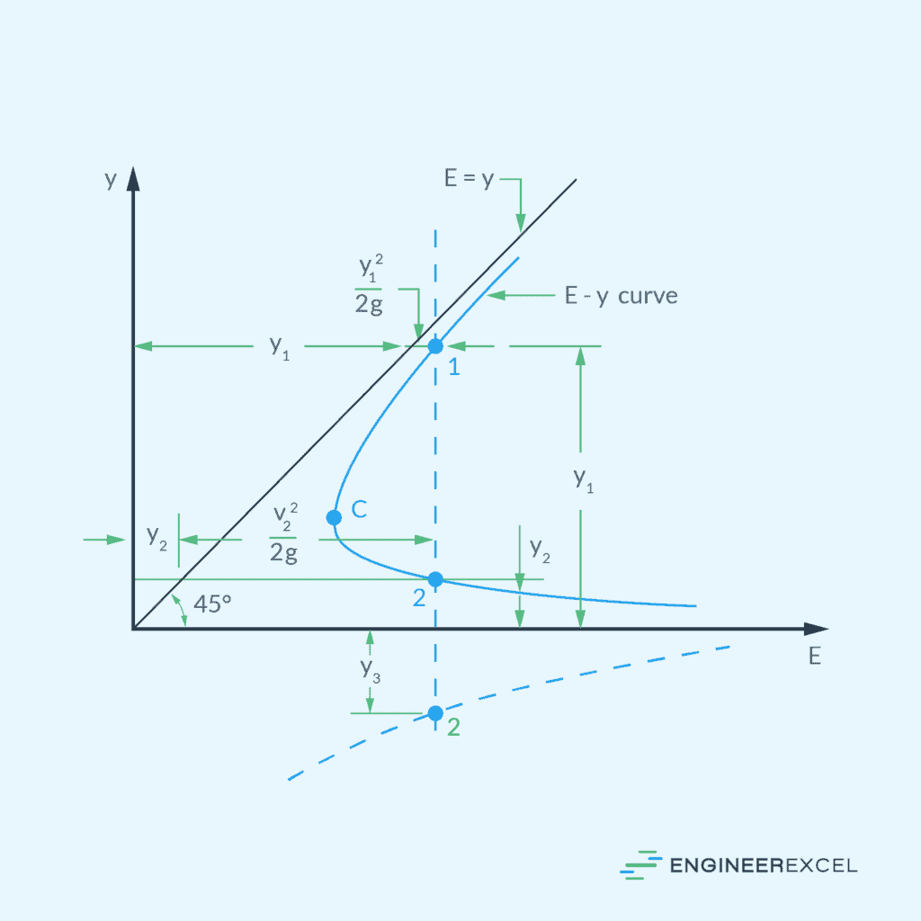
Specific Energy Diagram vs Flow Depth in Open Channels
Hydraulic Jump: Formation, Analysis, and Practical Applications
Understanding Critical Flow in Open Channels
Sharp Crested Weir: Open Channel Flow Measurement and Control
Hydraulic Radius: Calculation and Applications in Fluid Dynamics
Underflow Gate: Design Considerations for Efficient Water Management
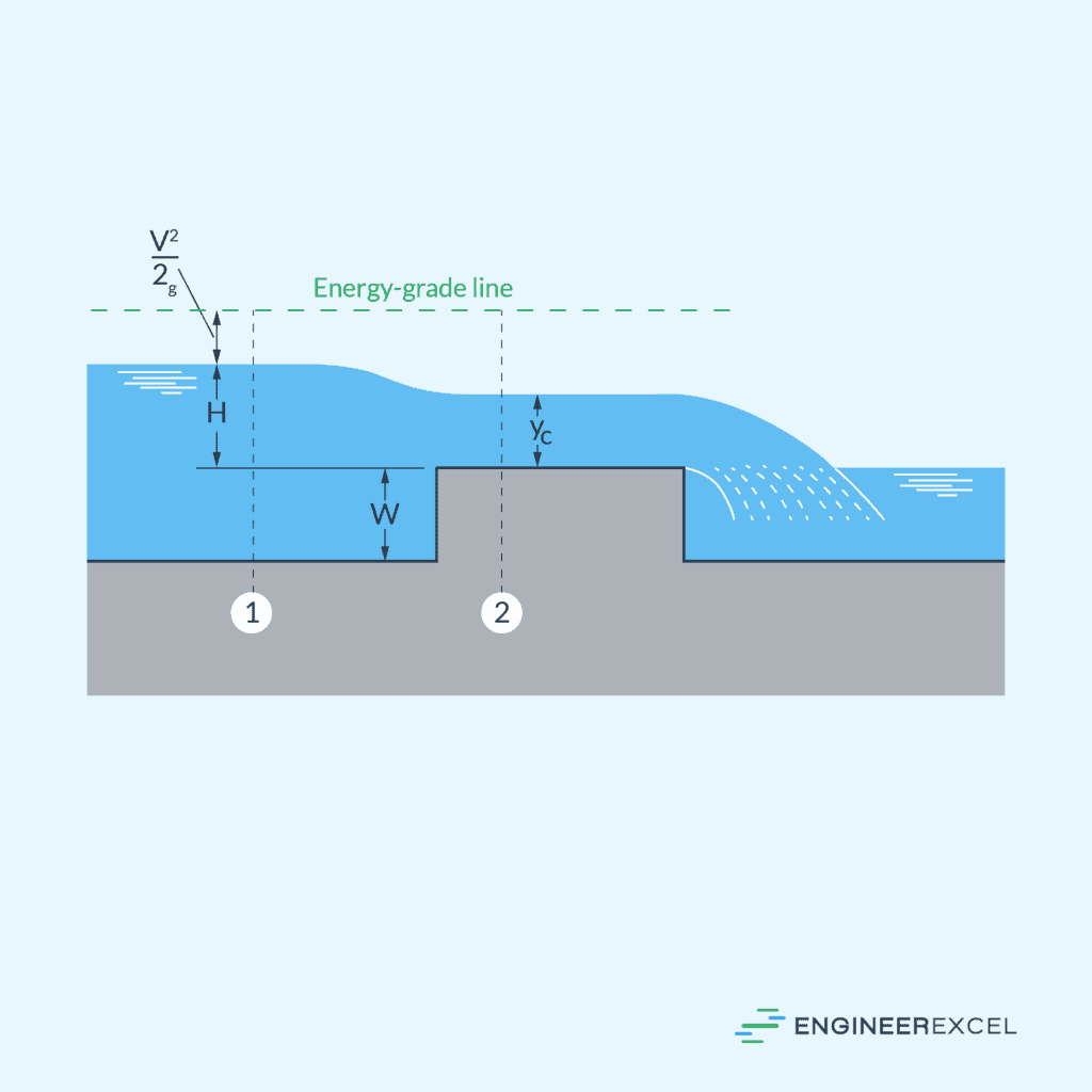
Broad Crested Weir Equation: Depth Control and Flow Measurement
Manning Equation: Velocity Calculation for Open Channel Flows
Rapidly Varied Flow: Analyzing Sudden Changes in Open Channel Flow
Wetted Perimeter: Understanding Its Effect on Channel Flow Dynamics
Chezy Equation: Application in Open Channel Flow Calculations
Best Hydraulic Cross Section: Optimal Design for Open Channel Flow
Weir Head: Analyzing Hydraulic Energy for Weir Flow
Weirs: Water Flow Control Structures in Open Channels
Gradually Varied Flow: Varying Surface Depth in Open Channels
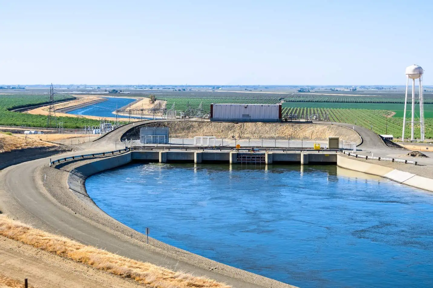
Open channel flow is the movement of fluid under the influence of gravity in natural or man-made channels, such as rivers, streams, and canals, with a free surface exposed to the atmosphere. Engineers often study this type of flow to design and manage water systems for purposes like irrigation, flood control, and water supply.
This article offers a comprehensive overview of open channel flow, covering the various types, hydraulic structures, and equations involved in open channel flow analysis.
Types of Open Channel Flow

Elevate Your Engineering With Excel
Advance in Excel with engineering-focused training that equips you with the skills to streamline projects and accelerate your career.
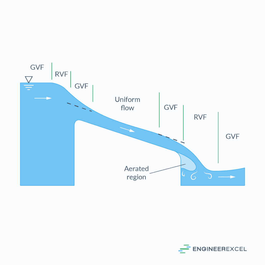
Open channel flow can be categorized into three major types based on the nature of the flow profile along the stream: uniform flow, gradually varied flow (GVF), and rapidly varied flow (RVF).

Uniform Flow
Uniform flow occurs when the depth of flow remains constant along the channel length. This happens when channel slope, roughness, and cross-section are consistent and the applied force due to the slope of the water surface is balanced by the resistance to flow. It is often idealized in engineering for simplicity but can be observed in long, straight channels with a constant cross-section.
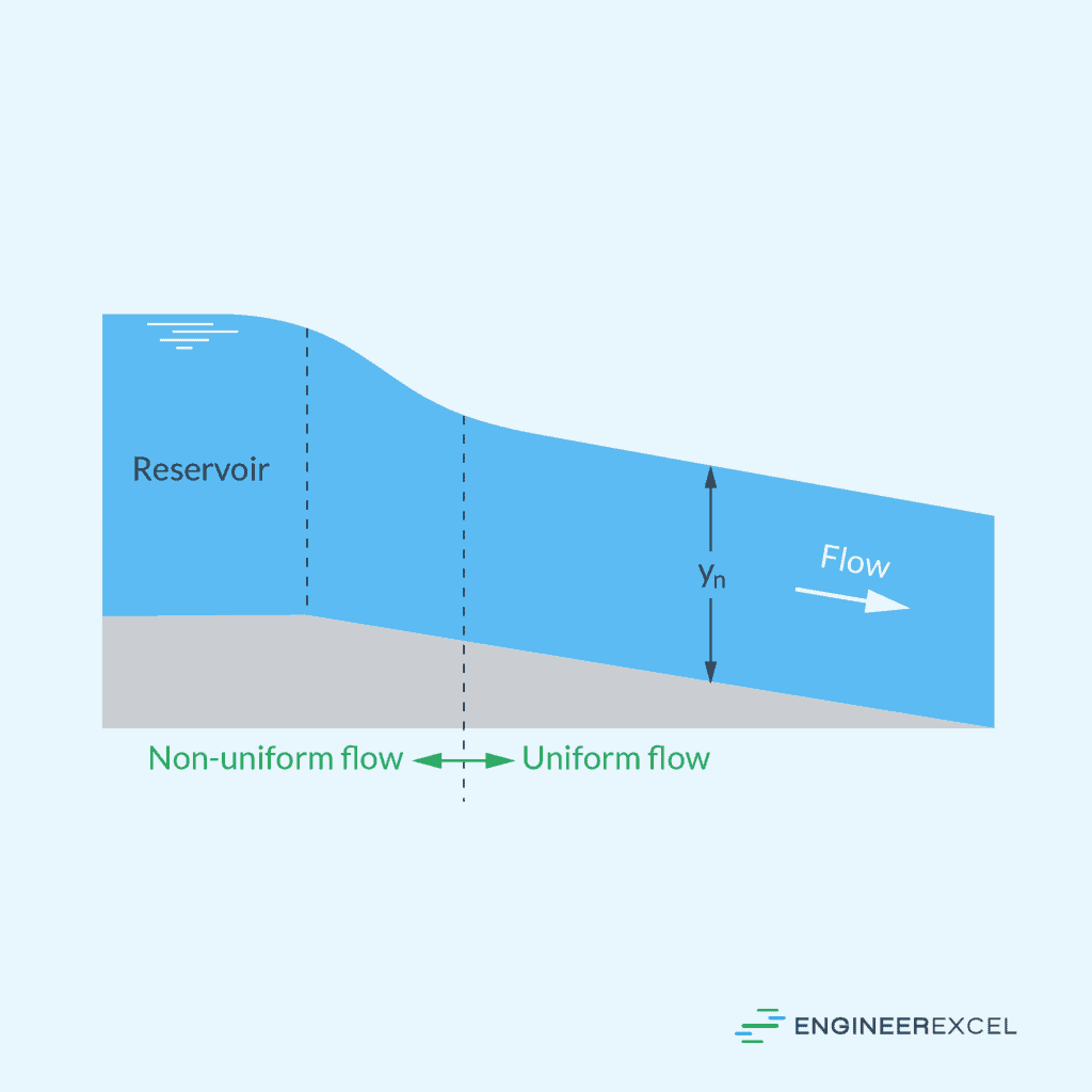
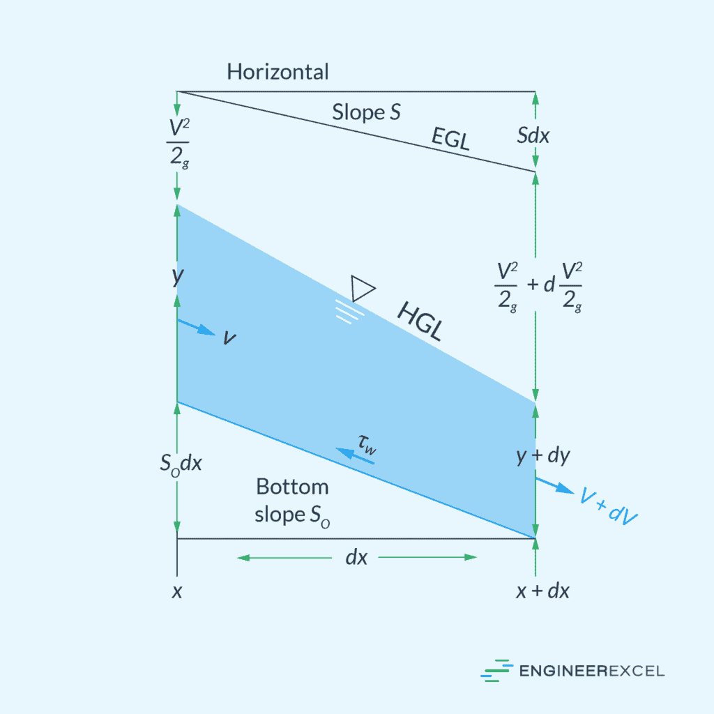
Gradually Varied Flow
GVF is characterized by the gradual change in the water depth. It occurs when channel conditions are not uniform or when external elements such as changes in slope or water discharge occur. Since changes in GVF take place over long distances, the velocity distribution can be assumed to be one-dimensional and the pressure distribution approximately hydrostatic.
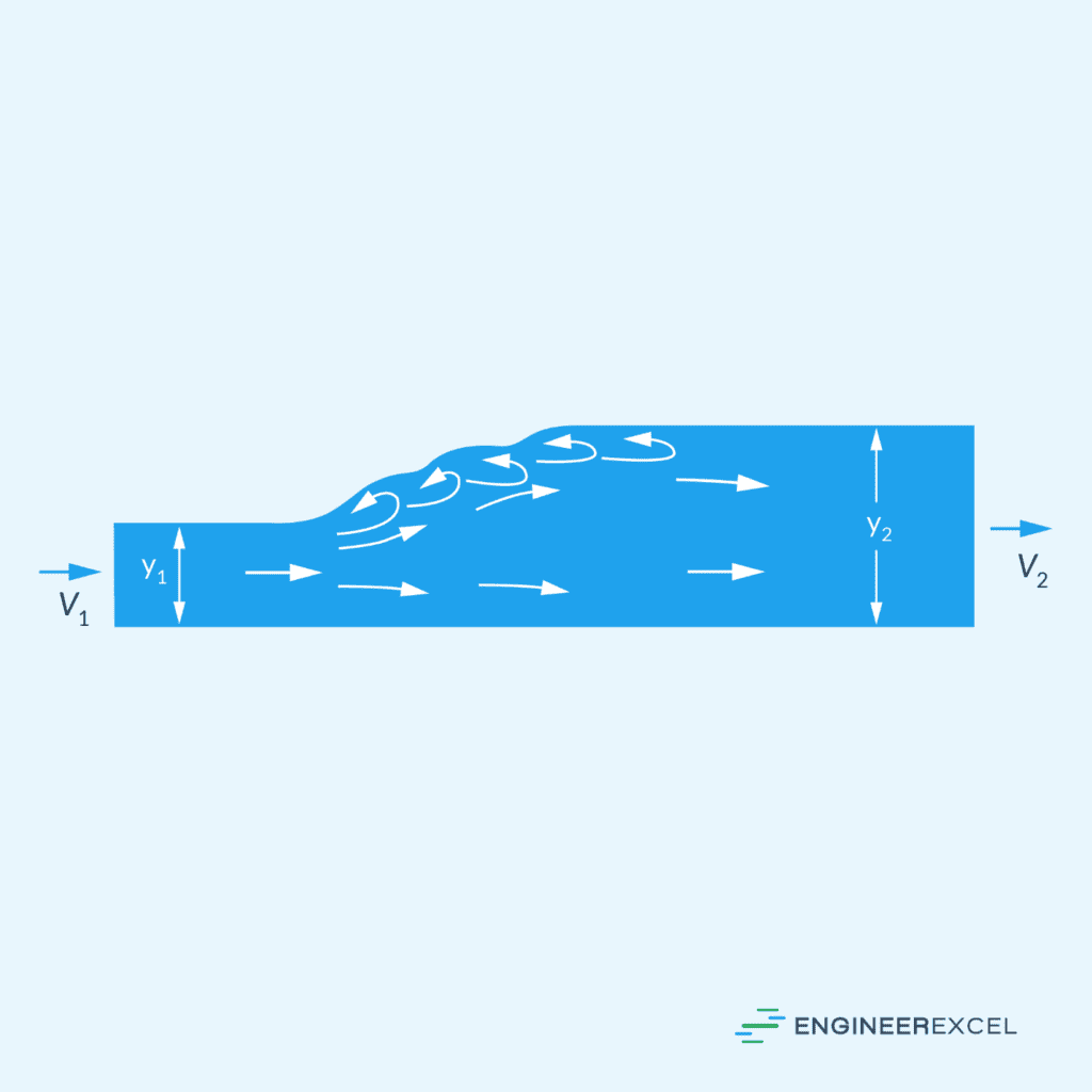
Rapidly Varied Flow
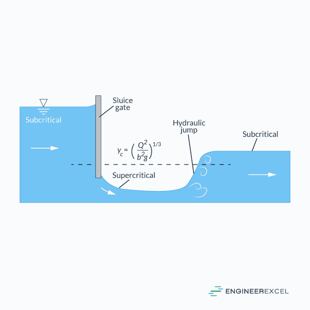
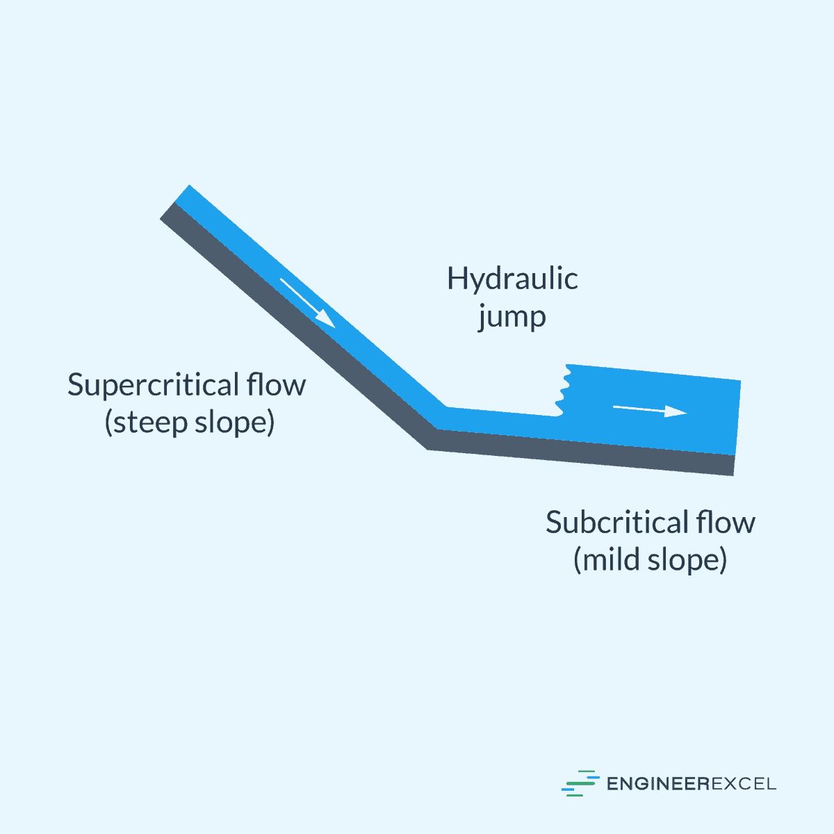
Contrary to gradual changes, RVF features abrupt changes in depth over a short distance. A common occurrence of RVF is a hydraulic jump, where the flow abruptly transitions from a high-velocity, low-depth state (super-critical) to a low-velocity, high-depth state (sub-critical), resulting in a distinct rise in the liquid surface.
This sudden change often requires careful engineering to manage energy and minimize potential damage to hydraulic structures. In RVF, the assumption of hydrostatic pressure distribution becomes invalid due to the flow’s complex behavior, making it difficult to analyze.
Classification Based on Froude Number
Another way to categorize open channel flow is through a dimensionless parameter called the Froude number. The Froude number is used to characterize the relative effects of inertial forces and gravitational forces in a flow. It defined as the ratio of the flow velocity to the wave celerity, as shown in the following equation:
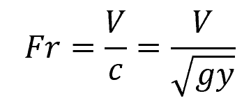
Where:
- Fr = Froude number [unitless]
- V = flow velocity [m/s]
- c = wave celerity [m/s]
- g = gravitational acceleration [9.81 m/s2]
- y = flow depth [m]
Depending on the value of the Froude number, the flow can be categorized as critical, subcritical, or supercritical flow.
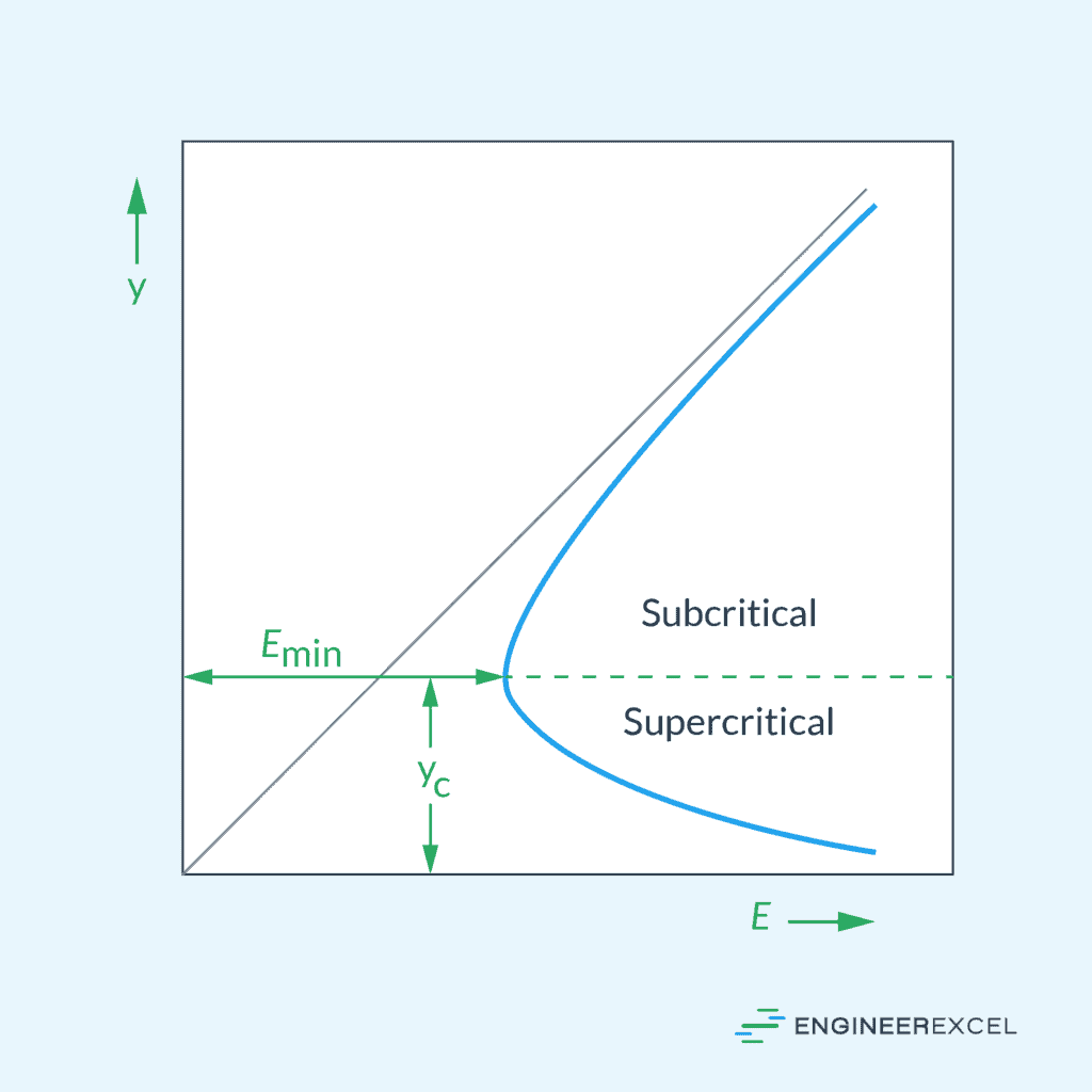
Critical Flow
Critical flow occurs when the Froude number is equal to one (Fr = 1). In this state, the flow velocity is equal to the wave propagation velocity, and the specific energy of the flow is at a minimum for a particular discharge.
This is a transitional phase where flow transitions from subcritical to supercritical conditions or vice versa. Engineers must be cautious when designing channels that operate near critical conditions due to the instability and rapidly changing flow characteristics.
Subcritical Flow
Subcritical flow is characterized by a Froude number less than one (Fr < 1). The flow velocity is less than the wave speed, leading to a tranquil and controlled movement of water. In this state, disturbances in the flow can travel upstream.
Hydraulic structures such as weirs and flumes are often designed to operate under subcritical conditions to maintain a predictable flow regime.
Supercritical Flow
Supercritical flow occurs when the Froude number exceeds one (Fr > 1). The flow is rapid and the wave speed is slower than the velocity of the flow, which prevents disturbances from moving upstream.
In supercritical flow, water surface profiles are steeper and have a flatter and more undulating appearance compared to subcritical flow. Engineers must carefully analyze supercritical flow to prevent structural damage and erosion in channels and spillways.
Open Channel Flow Equations
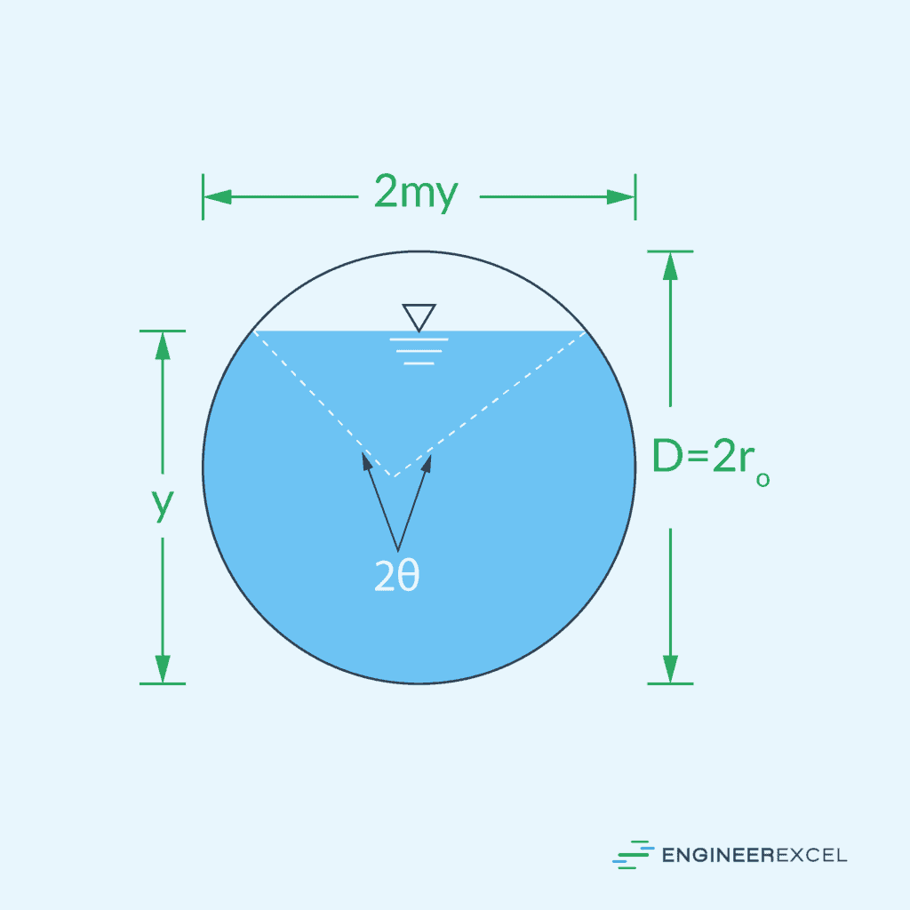
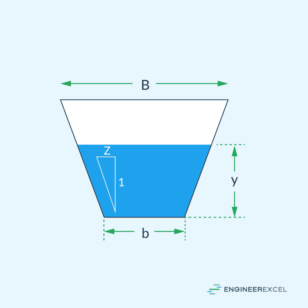
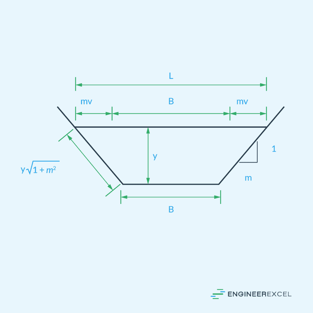
Hydraulic Radius
One of the key parameters in fluid mechanics used to characterize the efficiency of flow in open channels is the hydraulic radius. The hydraulic radius is the ratio of the cross-sectional area of a flowing fluid to the wetted perimeter of the conduit or channel through which the fluid is flowing. It is given by the formula:
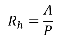
Where:
- Rh = hydraulic radius [m]
- A = area of flow [m2]
- P = wetted perimeter [m]
A larger hydraulic radius typically signifies a more efficient flow with reduced frictional losses, whereas a smaller hydraulic radius indicates a less efficient flow.
Chezy Equation
Developed by French engineer Antoine Chezy in the 18th century, the Chezy equation is one of the earliest formulas developed to estimate the mean flow velocity in an open channel. It is expressed as:
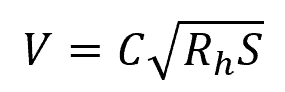
Where:
- C = Chézy coefficient [m1/2/s]
- S = slope of the channel [unitless]
The Chezy coefficient depends on the roughness and geometry of the channel, and its value ranges typically from 30 m1/2/s to 90 m1/2/s.
Manning Equation
Based on the Chezy equation, the more popular Manning equation was developed to provide a more accurate representation of the connection between the hydraulic radius and flow velocity. It is expressed as:
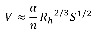
Where:
- n = Manning’s roughness coefficient [unitless]
The variable α is a conversion parameter that is equal to 1.0 for SI units and 1.486 for English units.
Manning introduced the Manning roughness coefficient as a new parameter, in contrast to the Chezy coefficient. The Manning roughness coefficient’s value depends only on the roughness of the channel surface, allowing for the creation of a standardized table of values. In contrast, the Chezy coefficient’s value changes with hydraulic radius and requires field measurements for determination.
Hydraulic Structures
Hydraulic structures, such as weirs and underflow gates, are essential for the control, diversion, and measurement of flow in open channels.
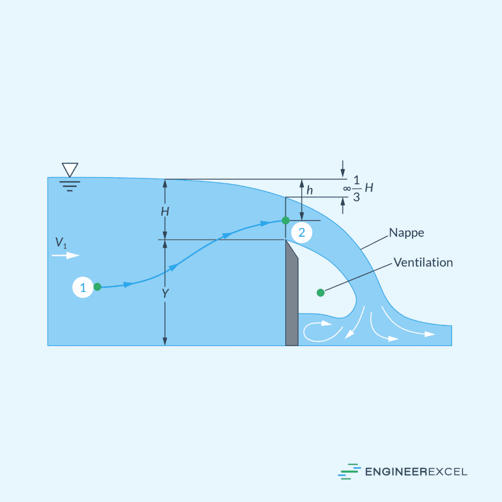
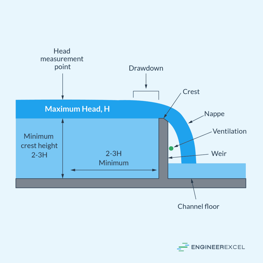
Weirs
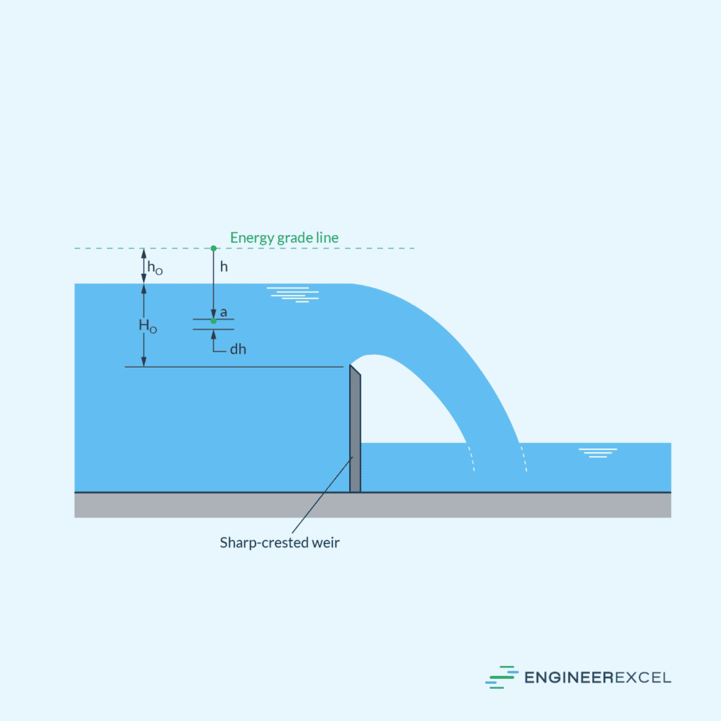
A weir is a barrier built across an open channel to control the flow level. They are commonly used for flow measurement purposes, as they allow for a straightforward calculation of flow rate based on the height of the water flowing over the barrier.
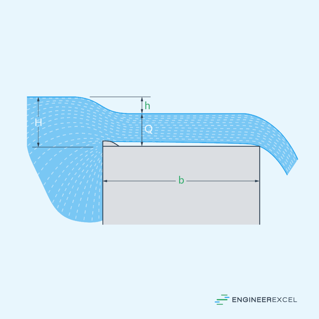
There are two major types of weirs: sharp-crested weirs and broad-crested weirs.
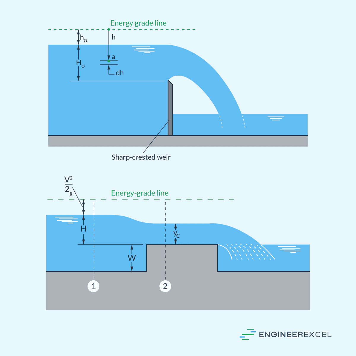
The key difference lies in their shape: a sharp-crested weir has a narrow, pointed crest, while a broad-crested weir has a wider crest. Sharp-crested weirs are commonly employed in smaller rivers and canals, while broad-crested weirs are generally more robust and utilized in medium to large rivers and canals.
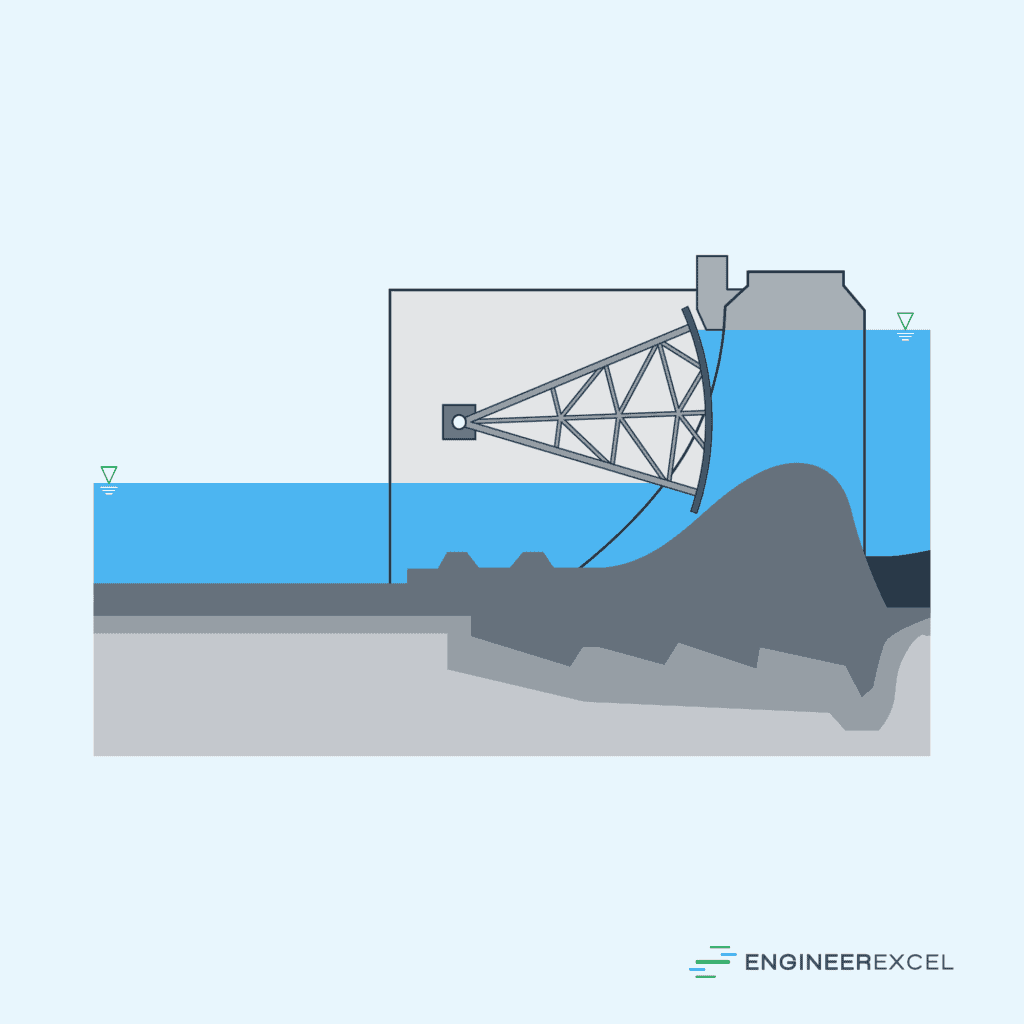
Underflow Gates
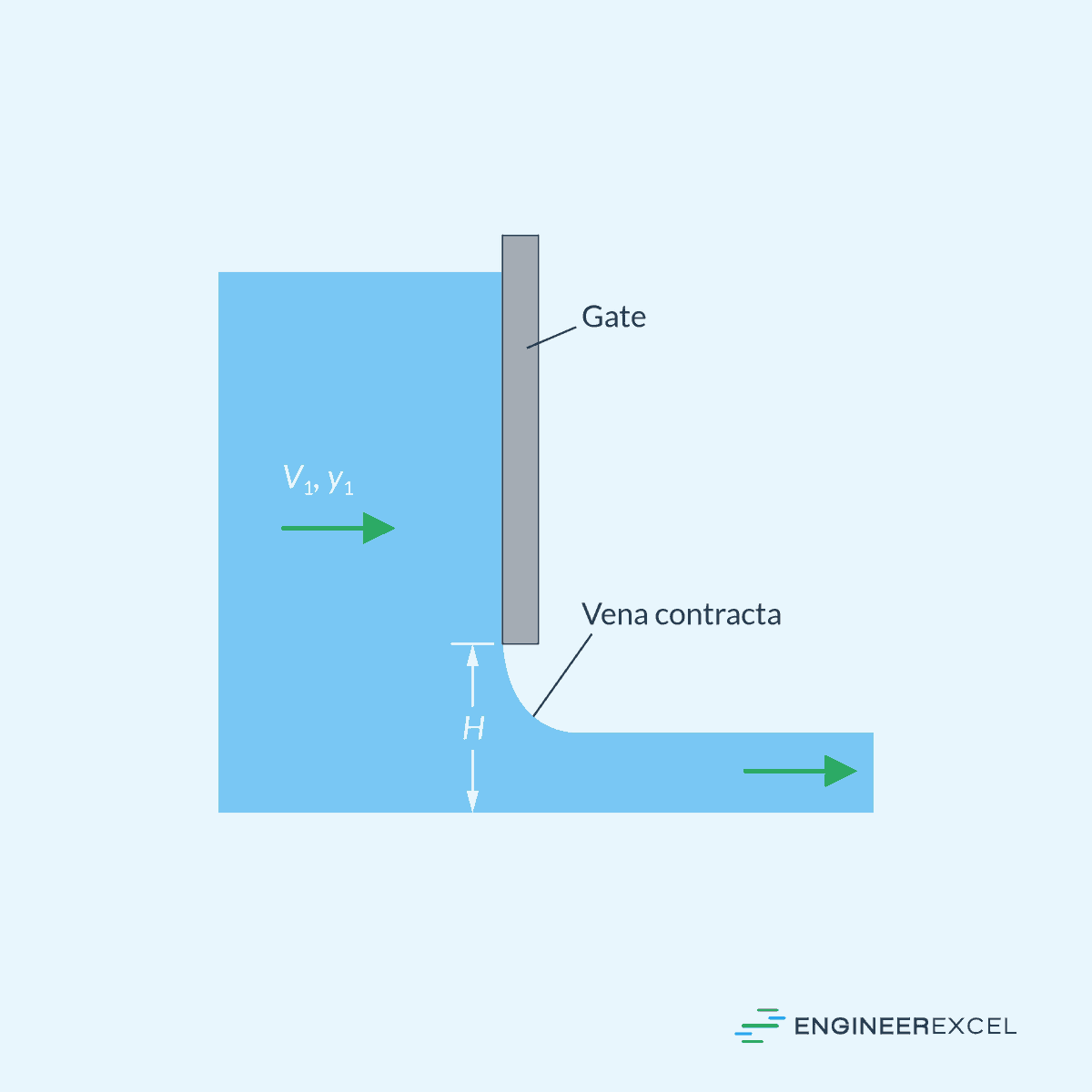
Typically made of metal or wood, an underflow gate consists of a movable barrier that can be raised or lowered to regulate the water level in an open channel. They are essential in managing water flow for various purposes, such as irrigation, flood control, or navigation. They can be manually operated or automated, and their design may include features such as racks, gears, or counterweights to facilitate precise control.