
Open channel flow refers to the flow of a liquid, usually water, in an open channel, such as a natural stream, river, or man-made canal. This type of flow occurs when the liquid has a free surface exposed to the atmosphere, so it is influenced by both gravity and atmospheric pressure.
In this article, we will discuss the essential equations of open channel flow, including its geometric parameters, the Froude number, and calculations for uniform flow, critical flow, gradually varied flow, and hydraulic jumps.
Open Channel Flow Geometry
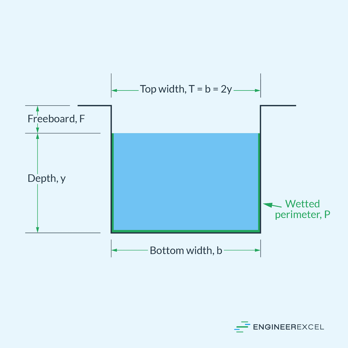
Before learning about the different equations that govern open channel flow, it’s important to first understand the parameters used to describe its geometry. Some of these parameters include depth, area, wetted perimeter, freeboard, hydraulic radius, and hydraulic depth.

Elevate Your Engineering With Excel
Advance in Excel with engineering-focused training that equips you with the skills to streamline projects and accelerate your career.
The depth (y) is the vertical distance from the free surface to the channel bottom. It is an important parameter that influences the hydraulic characteristics of the flow, including velocity and discharge. The depth of flow is often measured at a specific location within the channel and is an essential parameter in determining the required dimensions of the channel.
The area (A) in open channel flow is the cross-sectional area of the flow perpendicular to the flow direction. Knowing this area is essential for computing the flow rate as well as other hydraulic properties of the system.
This area can have various shapes such as trapezoidal, rectangular, or circular, with each shape offering specific advantages and disadvantages in different applications.
The wetted perimeter (P) is the total length of the channel boundary in contact with the flowing liquid. This perimeter has a significant influence on flow resistance and energy losses due to frictional forces. In practical applications, a larger wetted perimeter can lead to increased energy losses, affecting the efficiency and the design of hydraulic structures.
The hydraulic radius (Rh) is a parameter derived from the flow’s cross-sectional area and wetted perimeter. It is defined as the ratio of the area to the wetted perimeter:
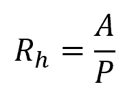
Where:
- Rh = hydraulic radius [m]
- A = cross-sectional area [m2]
- P = wetted perimeter [m]
The hydraulic radius helps in characterizing the efficiency of flow in open channels. A higher hydraulic radius indicates a more efficient flow, as it suggests a greater portion of the channel cross-section is actively contributing to conveying water, reducing the impact of frictional losses and promoting more effective energy transfer in the channel.
It is also useful to introduce a parameter called the hydraulic mean depth, which represents the flow’s average depth along the channel. It is mathematically expressed as:
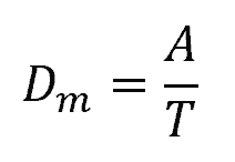
Where:
- Dm = hydraulic mean depth [m]
- T = top width at the free surface [m]
Hydraulic mean depth is particularly useful in scenarios where the flow exhibits non-uniformity in depth over the surface width.
Lastly, the freeboard (F) in open channel flow refers to the vertical distance between the water surface and the top of a channel or dam structure. It acts as a safety margin, providing extra space to accommodate variations in flow rates, waves, and debris without causing overflow or damage.
Froude Number Calculation
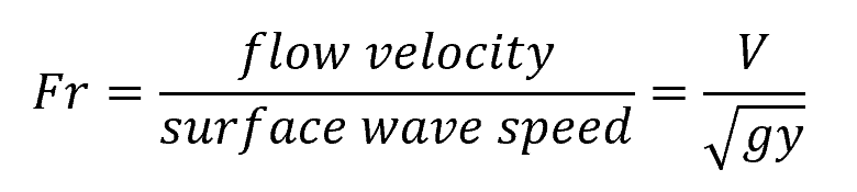
In open channel flow, the classification of flow types is essential for understanding and analyzing the fluid dynamics involved. One common method of classification is using the Froude number. The Froude number is a dimensionless parameter that compares inertial forces to gravitational forces and is defined as:
Where:
- Fr = Froude number [unitless]
- V = flow velocity [m/s]
- g = acceleration due to gravity [9.81 m/s2]
- y = flow depth [m]
Based on the Froude number, flows can be classified into three main categories: subcritical flow, critical flow, and supercritical flow. By analyzing the Froude number in open channel flows, engineers can predict flow behavior and develop the most effective designs and strategies.
Uniform Flow Equations
Chezy’s Formula
Chezy’s formula is an early simple equation used in the analysis of uniform open channel flows. It relates velocity in an open channel to the hydraulic radius and channel slope, as shown in the following equation:
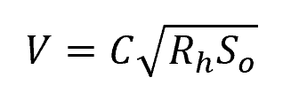
Where:
- C = Chézy coefficient [m1/2/s]
- So = slope of the channel [unitless]
For a given channel shape and bottom roughness, the Chezy coefficient (C) is constant and is related to friction factor by the following equation:
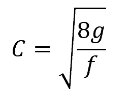
Where:
- f = friction factor [unitless]
Manning’s Equation
While Chezy’s formula is easy to use, it does not consider the impact of channel size on the value of the Chezy coefficient. In real channel tests, Robert Manning observed that the Chezy coefficient increased proportionally to the sixth root of the channel size. As a result, he introduced the Manning roughness coefficient, a new parameter solely determined by the channel’s roughness, and related to the Chezy coefficient through the following equation:
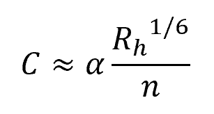
Where:
- n = Manning roughness coefficient [unitless]
Using the Manning roughness coefficient, the flow velocity in an open channel can be calculated using the Manning equation:
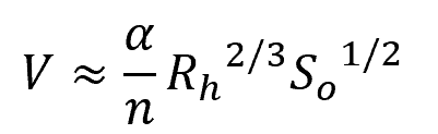
The variable α is a conversion parameter that is equal to 1.0 for SI units and 1.486 for English units.
Critical Flow Calculations
Specific Energy
The specific energy (E) in open channel flow is the sum of both kinetic energy and potential energy per unit weight of water. It can be expressed as:
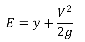
Where:
- E = specific energy head [m]
By calculating specific energy with respect to the flow depth and velocity, we can evaluate the stability and energy distribution of the flow. Critical flow occurs at the point of minimum specific energy.
Critical Depth
Critical depth (yc) is the flow depth at critical flow conditions. It can be found by differentiating the specific energy equation with respect to depth and setting it to zero. This results in the following equation:
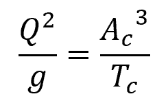
Where:
- Q = flow rate [m3/s]
- Ac = cross-sectional flow area at critical flow conditions [m2]
- Tc = width of the channel section at the free surface at critical flow [m]
The critical depth (yc) can be plugged into the above equation in lieu of Ac and Tc, depending on the shape of the channel.
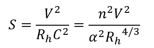
Gradually Varied Flow Equation
Gradually varied flow (GVF) occurs when the flow depth and velocity in an open channel change gradually along the channel length. The change in flow depth for a gradually varied flow can be described using the following equation:

Where:
- S = slope of the energy grade line [unitless]
- α = kinetic energy correction factor [unitless]
- T = width of the channel [m]
In the above equation, the slope of the energy grade line (S) is equivalent to the slope of a uniform flow at the same discharge. Hence, it can be derived from the Chezy equation or the Manning equation as follows:
Hydraulic Jump Equations
A hydraulic jump occurs when there is a sudden increase in depth in an open channel flow, often caused by a decrease in flow velocity and an increase in energy loss. This phenomenon is mainly observed in steep channels where the flow transitions from supercritical to subcritical conditions.
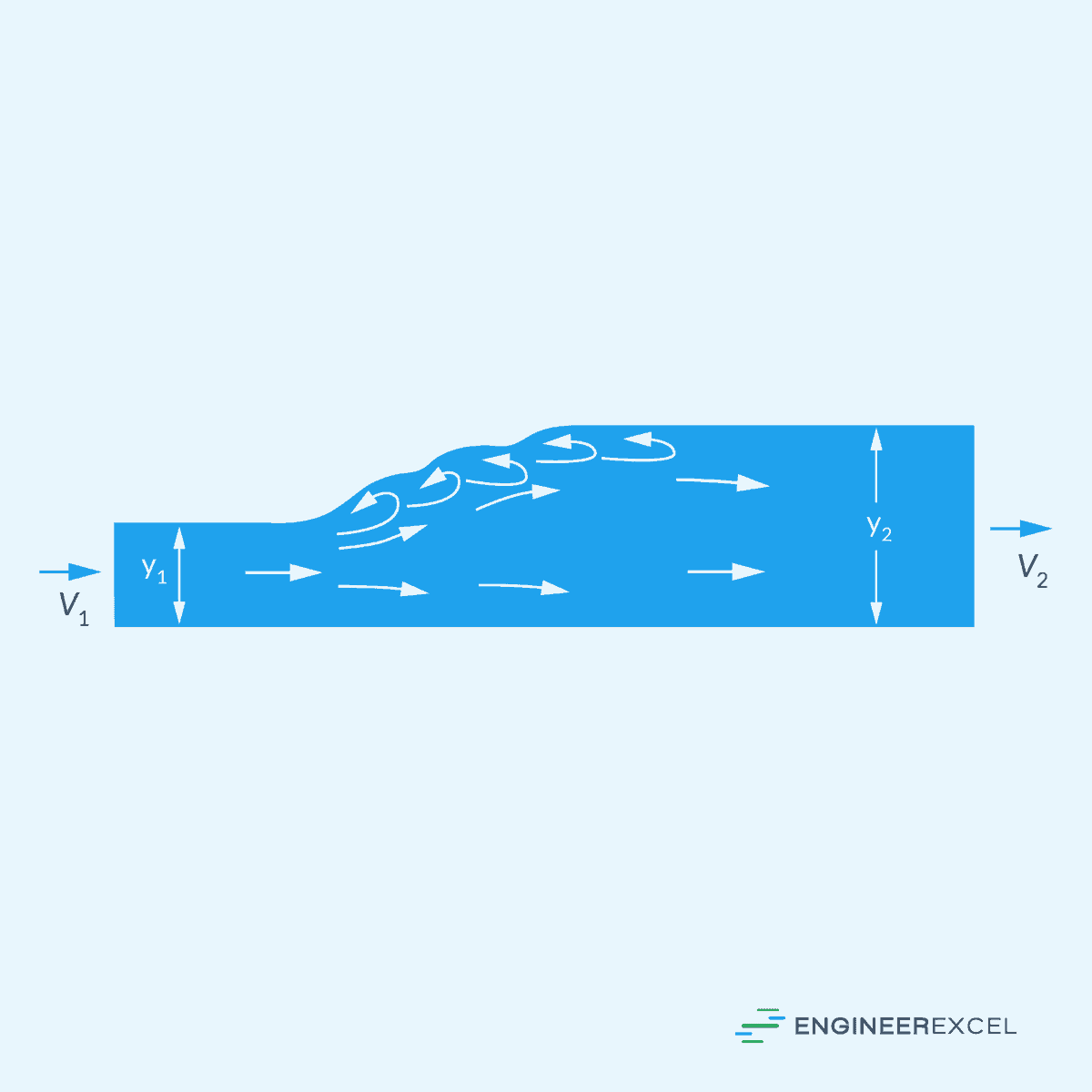
Change in Depth
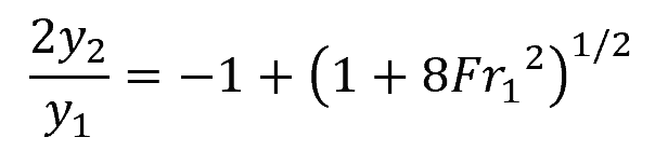
The change in depth in a hydraulic jump can be calculated using the following equation:
Where:
- y1 = initial depth [m]
- y2 = final depth [m]
- Fr1 = Froude number before the jump [unitless]
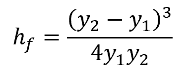
Energy Losses
Energy losses in a hydraulic jump are primarily due to the turbulence caused by the sudden change in depth. The energy loss can be calculated using the following equation:
Where:
- hf = dissipation head loss [m]