
Varied flow in open channels refers to the condition where the water velocity changes along the channel’s length, resulting in non-uniform flow patterns. This phenomenon is commonly observed in natural watercourses, such as rivers, where factors like channel geometry and topography lead to diverse flow velocities.
In this article, we will discuss the two main types of varied flow, Gradually Varied Flow (GVF) and Rapidly Varied Flow (RVF), and delve into the analysis and characteristics of each type.
Understanding Varied Flow in Open Channels
In the context of open channel flow, the term “varied flow” refers to a scenario where the flow properties, such as velocity and depth, change along the length of the channel at a specific moment. This stands in contrast to uniform flow, where such properties remain constant over a given length of the channel at any instant.
Varied flow can be broadly classified into two main types:

Elevate Your Engineering With Excel
Advance in Excel with engineering-focused training that equips you with the skills to streamline projects and accelerate your career.
- Gradually Varied Flow (GVF): Occurs when the depth of the flow changes at a gradual rate along the channel’s length.
- Rapidly Varied Flow (RVF): Identified by a significant change in depth over a short distance.
In GVF, water depth and velocity change progressively with the distance along the channel. The assumption here is that transitions occur over a considerable length, allowing the pressure to remain hydrostatic. As a result, the energy gradient, water surface, and bed slope all differ but change subtly.
Conversely, RVF features abrupt changes in water depth and velocity. These shifts can result from alterations in channel slope, cross-sectional area, or due to obstructions like weirs and gates. Because of these rapid transitions, the water pressure in RVF may deviate from the hydrostatic assumption, especially in parts of the flow where curvature is present.
These distinctions are critical when considering the computation of discharge rates and the forces on channel boundaries. While GVF allows for relatively straightforward calculations using average velocities, RVF necessitates an in-depth understanding of complex velocity and pressure distributions that might only be obtained through empirical measurements or model studies. Understanding these two types of flows is vital for the accurate design and management of water conveyance structures.
Gradually Varied Flow
Gradually Varied Flow (GVF) represents a condition where the change is not abrupt, allowing for a steady adjustment in the velocity and hydraulic depth. Applications of GVF analysis are common where the slope of the channel bed is gentle and downstream changes are modest.
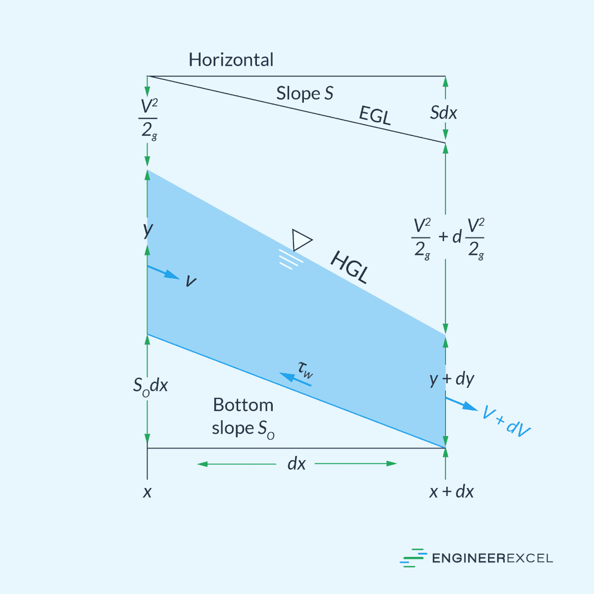
Calculating the depth of flow in channels experiencing gradually varied flow (GVF) involves understanding the balance between gravitational forces and resistance due to channel friction. The fundamental equation used for this is:
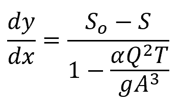
Where:
- y = depth of flow [m]
- So = slope of the channel bottom [unitless]
- S = slope of the energy grade line [unitless]
- α = kinetic energy correction factor [unitless]
- T = width of the channel [m]
- g = gravitational acceleration [9.81 m/s2]
Alternatively, this equation can be written in terms of the Froude number:
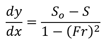
- Fr = Froude number [unitless]
This approach differentiates between subcritical flow (Fr < 1) and supercritical flow (Fr > 1), which influences the sign of the equation’s denominator and subsequently the calculation’s directionality.
In the above equations, the slope of the energy grade line (S) reflects the energy dissipation and can be derived from uniform flow equations, such as the Chezy Formula and Manning’s Equation, as follows:
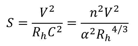
Where:
- Rh = hydraulic radius [m]
- C = Chezy coefficient [unitless]
- n = Manning roughness coefficient [unitless]
Gradually varied flow can be categorized into five channel slope classifications (steep, critical, mild, horizontal, and adverse) based on the comparison between the actual channel slope (So) and the critical slope (Sc) or the slope of the critical depth, as illustrated in the diagram below.
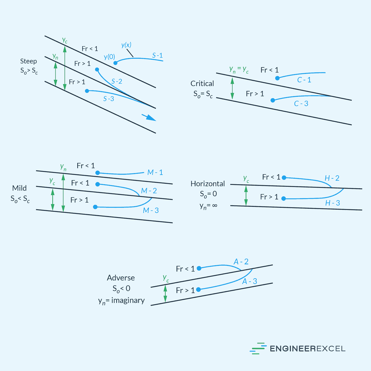
These classifications result in twelve possible solution curves, with each type denoted by a letter representing the slope type (S, C, M, H, A) and a number (1, 2, 3) indicating the initial point’s position in relation to the normal depth (yn) and the critical depth (yc).
In Type 1, the initial point is above both yn and yc, leading to the water depth becoming even deeper than yn and yc as it moves along the channel. Type 2 solutions occur when the initial point lies between yn and yc, causing the water depth to gradually approach the lower of yn or yc asymptotically. In Type 3 cases, the initial point is below both yn and yc, and the solution curve gradually approaches the lower of yn or yc.
Rapidly Varied Flow
Rapidly Varied Flow (RVF), by contrast, is characterized by sudden changes in depth over a relatively short distance. This type of flow commonly occurs at structures within the channel like weirs or spillways.
One of the most common examples of a rapidly varied flow is the hydraulic jump, illustrated in the diagram below.
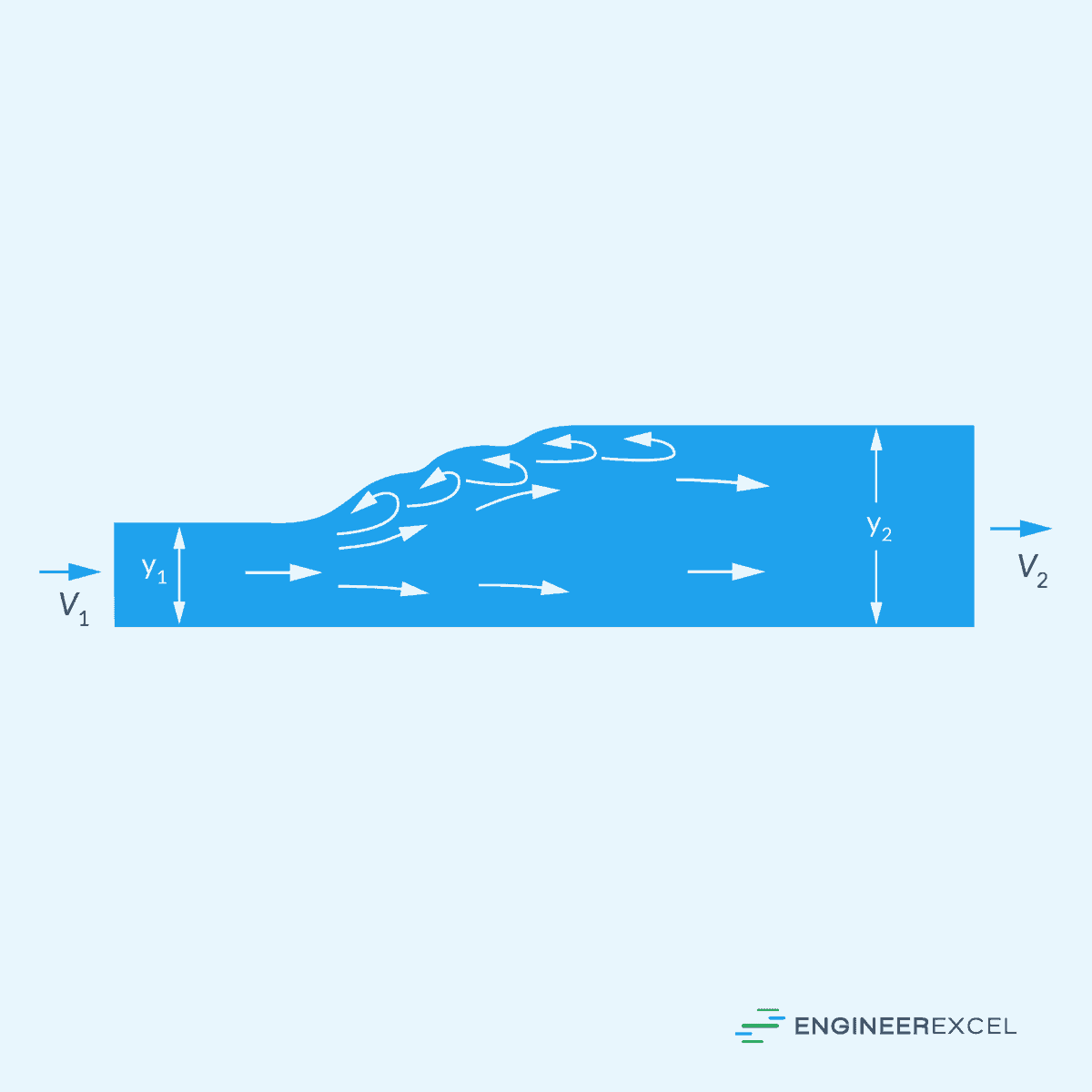
A hydraulic jump is characterized by a rapid increase in water depth and turbulence, typically occurring when supercritical flow transitions to subcritical flow. Given initial conditions at the supercritical state, the final flow depth at the subcritical state can be calculated using the following equation:
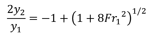
Where:
- y1 = initial depth [m]
- y2 = final depth [m]
- Fr1 = Froude number before the jump [unitless]
Once the final depth is found, the final velocity can be calculated using the continuity equation:
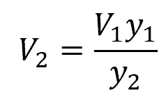
Where:
- V1 = initial flow velocity [m/s]
- V2 = final flow velocity [m/s]
During a hydraulic jump, energy is dissipated due to turbulence. This energy loss can be approximated using the following equation:
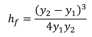
Where:
- hf = dissipation head loss [m]