
Sharp-crested weirs are hydraulic structures with a thin, sharp-edged crest that protrudes above the water surface in channels or rivers. They are commonly used to measure and control the flow of water by creating a predictable and easily quantifiable flow rate. In this article, we will cover sharp-crested weirs, including their types, calculations, theory, and practical considerations for flow measurement.
What is a Sharp-Crested Weir
A weir is a hydraulic structure commonly used in open channels for various purposes such as flow regulation, flow measurement, and sediment control. Sharp-crested weirs are one type of weir, consisting of a thin plate mounted perpendicular to the flow direction.
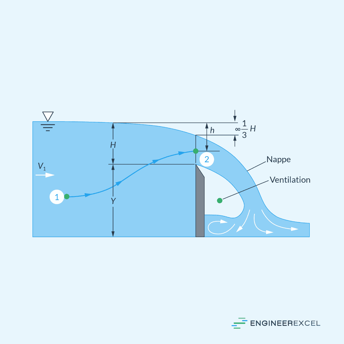
The top of the plate has a beveled, sharp edge that allows the water to spring clear from the plate. The flow upstream is subcritical, accelerates to critical near the top of the weir, and spills over into a supercritical sheet of water called the nappe, as shown in the diagram below.

Sharp-crested weirs are known for their precise measurement capabilities and are widely used for flow measurement applications.

Elevate Your Engineering With Excel
Advance in Excel with engineering-focused training that equips you with the skills to streamline projects and accelerate your career.
On the other hand, broad-crested weirs have a wide, horizontal crest with a blunt edge, which slows down the water flow and causes it to spread out over the crest. While both types of weirs can be used for flow measurement, sharp-crested weirs are preferred when accurate discharge measurements are required.
Types of Sharp-Crested Weirs
There are several types of sharp-crested weirs, differing in their shape and application. The most common types include rectangular, triangular (V-notch), and trapezoidal (Cipolletti) weirs.
Rectangular Weirs
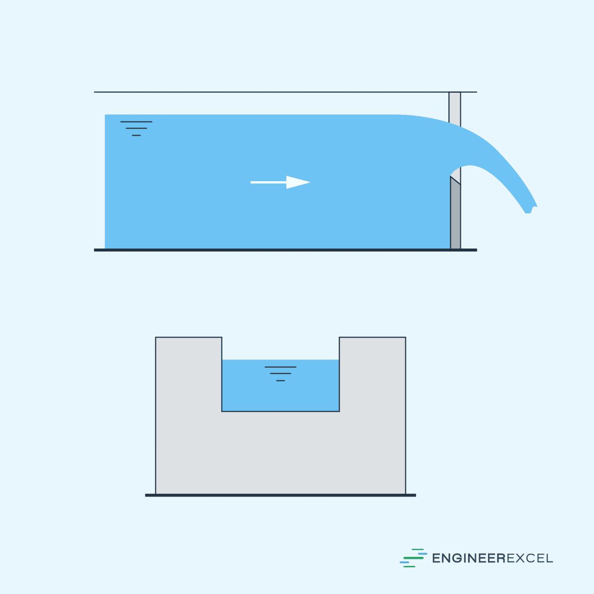
Rectangular Weirs are the simplest type of sharp-crested weir. They consist of a horizontal crest with a rectangular opening. There are two main types of sharp-crested rectangular weirs: contracted and suppressed.
In a contracted weir, the width of the weir is less than the width of the channel in which it is installed. Hence, the flow approaches the weir through a contracted section.
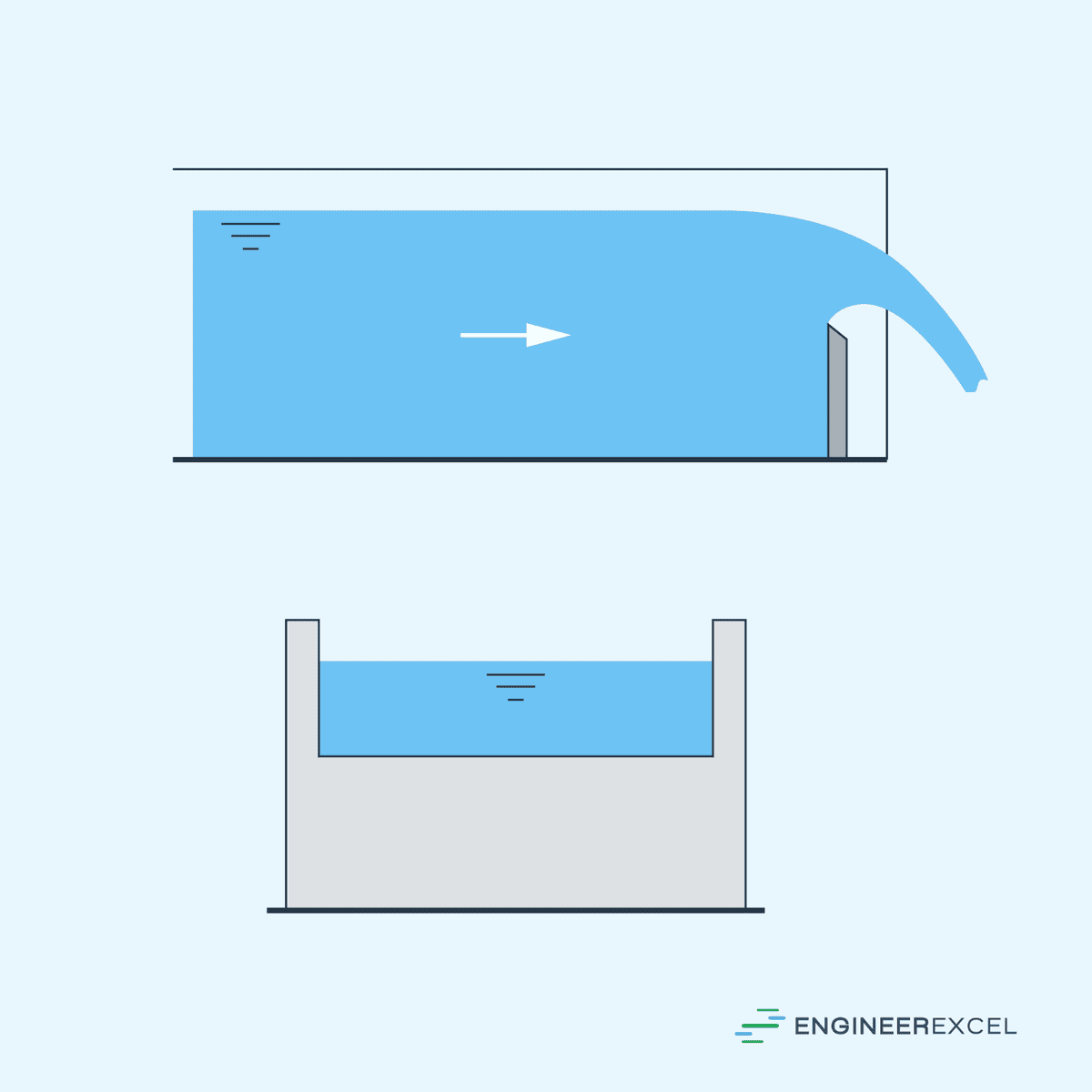
On the other hand, in a suppressed weir, the width of the weir is equal to the width of the channel in which it is installed. Hence, the flow approaches the weir without any contraction.
These are illustrated in the diagrams below.
Triangular Weirs
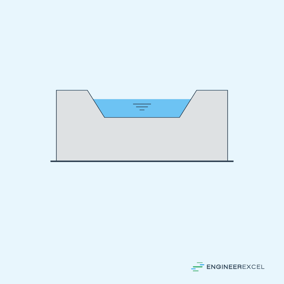
Triangular Weirs or V-notch Weirs have a V-shaped opening with an angle usually ranging from 10° to 90°, as shown in the diagram below. These weirs are particularly useful for measuring low flow rates.

Trapezoidal Weirs
Trapezoidal Weirs, also called “Cipolletti Weirs,” have a trapezoidal opening with a slightly inclined side to achieve a constant head-discharge relationship. The side-slope ratio of the trapezoidal weir determines its efficiency in measuring flow.
Sharp-Crested Weir Calculations
Flow Velocity Over the Weir
Neglecting the viscous losses and assuming that the pressure at all points in the nappe is atmospheric, the flow velocity at any point above the weir crest can be calculated using the following equation:
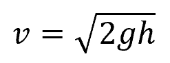
Where:
- v = flow velocity over the weir [m/s]
- g = gravitational acceleration [9.81 m/s2]
- h = vertical distance below the energy grade line [m]
Sharp-Crested Weir Theory
It was found that the flow reduces to two-thirds of the total depth above the crest right before it exits the weir. Therefore, the theoretical volumetric flow rate per unit width can be calculated by integrating the product of the velocity and depth of flow (above the crest), and getting two-thirds of this value. The resulting equation is shown below:
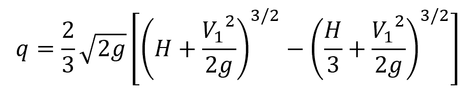
Where:
- q = flow rate per unit width [m2/s]
- H = maximum head above the crest [m]
- V1 = subcritical flow velocity at the channel [m/s]
Normally the upstream velocity head is neglected so that the expression reduces to:
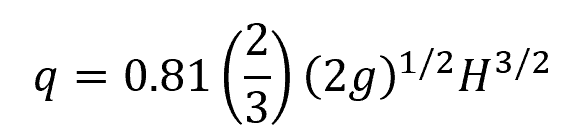
Experimental Weir Flow Rate
Although the above equation for flow rate is functionally correct, the coefficient 0.81 is too high compared to what is observed experimentally. In practice, the flow rate can be affected by environmental factors such as roughness of weir surfaces and air entrainment. To account for these factors, experiments are conducted to calibrate weirs and adjust flow rate using a dimensionless parameter called the discharge coefficient.
The formula for flow rate then becomes:
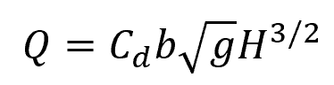
Where:
- Q = flow rate [m3/s]
- Cd = discharge coefficient [unitless]
- b = crest width [m]
Discharge Coefficient
The discharge coefficient is typically experimentally determined and may vary with the weir geometry, Reynolds number, and Weber number. The following equation can be used to estimate the discharge coefficient for wide ventilated sharp crests:
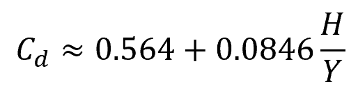
Where:
- Y = height of the crest with respect to the channel bottom [m]
This equation is valid for H/Y values less than or equal to 2.
Flow Measurement
Sharp-crested weirs are commonly used in open-channel flow measurement due to their simplicity and predictable flow patterns.
To begin with, the weir must be placed perpendicular to the flow and the weir crest must be straight and level. Maintaining a straight channel upstream from the weir is essential, with the straight length being at least 10 times the length of the weir crest. Installing the weir at right angles to the direction of water flow will ensure that the head measurement is unaffected by any irregularities in the channel shape.
Utilizing tables or graphs for discharge coefficients based on specific weir geometries can enhance the accuracy of the flow measurement. Moreover, it is important to check for sediment or debris accumulation, as they can affect the flow patterns and result in inaccurate measurements.
For accurate measurements and effective performance, sharp-crested weirs require proper venting of the nappe underside to maintain atmospheric pressure. Failure to ensure adequate venting may lead to incorrect pressure assumptions and skewed discharge calculations.