
Rapidly varied flow in an open channel refers to a condition where the water surface undergoes abrupt changes over a short distance, often due to sharp contractions, expansions, or abrupt changes in channel slope.
The complex interactions between flow velocity, depth, and channel geometry result in rapid and significant alterations in the flow regime. This article will explore rapidly varied flow, covering the conservation laws, hydraulic jumps, and its applications in water engineering.
What is a Rapidly Varied Flow?
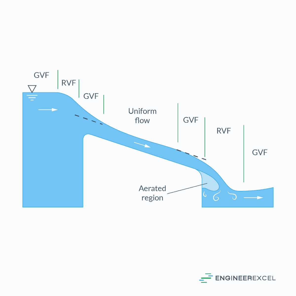
Rapidly varied flow (RVF) is a type of fluid flow where the streamlines have sharp curvatures, leading to a non-hydrostatic pressure distribution. This phenomenon differs from uniform flow and gradually varied flow (GVF), which assume hydrostatic pressure distribution. Rapidly varied flows often occur when there are sudden changes in channel geometry, causing the flow depth to change rapidly and sometimes discontinuously, such as in a hydraulic jump.

Elevate Your Engineering With Excel
Advance in Excel with engineering-focused training that equips you with the skills to streamline projects and accelerate your career.
In RVFs, the assumption of hydrostatic pressure distribution becomes invalid due to the flow’s complex behavior and interactions with obstacles or discontinuities, making it challenging to analyze using the same approach as parallel flows. Boussinesq and Fawer assumptions have been utilized for analyzing RVFs. The former assumes that the vertical flow velocity varies linearly from the channel bottom to the maximum at the free surface, while the latter assumes an exponential variation in the vertical flow velocity.
Since RVFs occur over short distances, the losses due to shear at channel boundaries are generally small and can be neglected in most analyses. However, sudden changes in channel geometry may lead to flow separation, forming eddies and swirls that complicate the flow pattern. This complexity makes it difficult to generalize the velocity distribution across a section and quantify energy and momentum coefficients, which usually assume higher values than unity. The formation of rollers, eddies, and separation zones also challenges the definition of flow boundaries and determination of average flow variables for a cross-section.
For engineers, it is important to recognize cases where rapidly varied flows occur and adapt their analysis methodologies accordingly. Since many rapidly varied flows have been mainly investigated experimentally, empirical relationships, charts, and diagrams can be found as helpful resources for handling typical design applications in such cases.
Conservation Laws in Rapidly Varied Flow
Conservation of Mass
The volumetric rate of flow through a cross section can be mathematically expressed as:
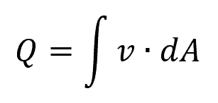
Where:
- Q = volumetric flow rate [m3/s]
- v = flow velocity [m/s]
- dA = flow area [m2]
The dot product indicates that the flow velocity (v) should be perpendicular to the flow area (dA). In the case of rapidly varied flow, where the flow can be complex and the direction of the velocity may vary in different parts of the depth, we cannot simply calculate the volumetric flow rate based on the mean flow velocity. Therefore, understanding the velocity distribution is essential for computing the rate of discharge.
Conservation of Momentum
To account for the nonuniform velocity distribution, we may write the equation for the rate of momentum flux as follows:
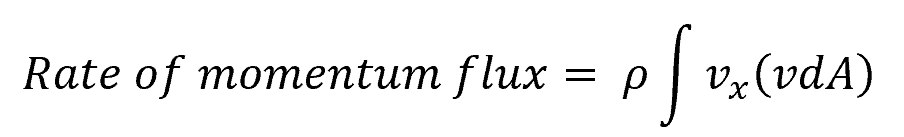
Where:
- ρ = density of the fluid [kg/m3]
- vx = flow velocity in the x direction [m/s]
To evaluate this equation, the velocity distribution and its component in the x direction should be known.
Conservation of Energy
In the case of rapidly varied flow, the pressure distribution may not be hydrostatic in regions of curvilinear flow due to local accelerations. Therefore, understanding the pressure distribution is essential to calculate the force acting on a section. This distribution may not be known without measurements on the prototype or tests on a hydraulic model.
As the pressure distribution is not hydrostatic, the energy flux at any section can be expressed in the power form as:
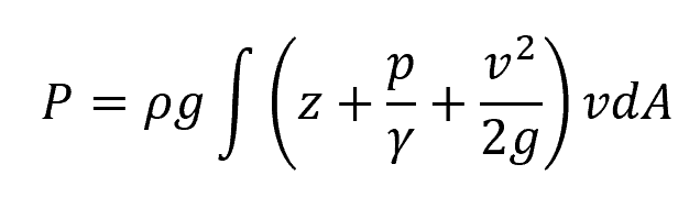
Where:
- P = energy flux at a section [W]
- g = gravitational acceleration [9.81 m/s2]
- z = elevation [m]
- p/γ = pressure head [m]
Both the velocity and pressure distribution should be known at the section in order to evaluate the above equation.
Hydraulic Jump
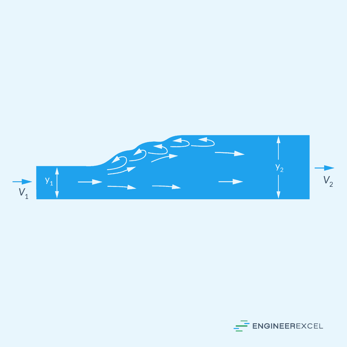
The most common example of a rapidly varied flow is a hydraulic jump— a phenomenon where a rapid change occurs in the flow regime from supercritical to subcritical flow. This change is typically caused by an abrupt increase in the channel slope, leading to a sudden energy dissipation and increase in fluid depth. Hydraulic jumps are commonly observed in rivers, spillways, and other open channels where rapidly flowing water encounters an obstacle or a transition zone.
Change in Depth
The change in depth during a hydraulic jump can be calculated using the following equation:
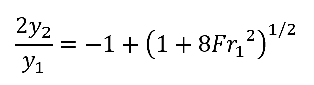
Where:
- y1 = initial depth [m]
- y2 = final depth [m]
- Fr1 = Froude number before the jump [unitless]
Change in Velocity
The change in velocity during a hydraulic jump can be determined using the continuity equation:
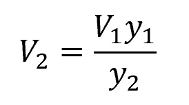
Where:
- V1 = initial flow velocity [m/s]
- V2 = final flow velocity [m/s]
Energy Loss
The energy loss during a hydraulic jump can be approximated using the following equation:
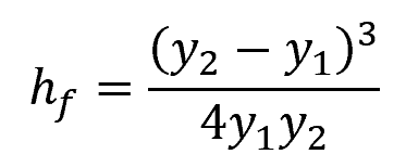
Where:
- hf = dissipation head loss [m]
Applications of Rapidly Varied Flow
Rapidly varied flow has several applications in water engineering, including channel transitions, weirs, spillways, and energy dissipators.
Channel Transitions
Channel transitions occur when an open channel’s cross-sectional area or slope varies, resulting in rapidly varied flow. These adjustments may include expansions, contractions, horizontal and vertical bends. Transitions are often necessary in real-life applications like river training, flood protection, and urban drainage systems.
Weirs
Weirs are hydraulic structures built across open channels to regulate upstream water levels, measure discharge, or redirect water flow. The flow over weirs becomes rapidly varied flow due to the sudden drop in channel depth. Weir design covers various types, such as rectangular, V-notch, and broad-crested weirs, each with specific hydraulic characteristics.
Spillways
Spillways are engineered channels or structures used to convey excess water from reservoirs, lakes, or dams to avoid overtopping and failure. The rapid flow variation in spillways occurs due to the abrupt change in flow depth and velocity resulting from a sudden drop in elevation. Various spillway types serve distinct purposes, like ogee, chute, drop, and siphon spillways.
Energy Dissipators
Energy dissipators are hydraulic structures utilized to reduce water velocity and dissipate the energy in rapidly varied flow, protecting downstream channels from erosion and sediment transport. Energy dissipators are typically placed at the end of weirs, spillways, or pipe outlets. Examples of energy dissipators include stilling basins, impact-type dissipators, and hydraulic jump basins.