Specific energy refers to the energy per unit weight of fluid in an open channel flow, comprising the sum of the kinetic and potential energies. It is a critical parameter in hydraulic engineering, influencing the flow behavior and indicating the balance between the channel slope, velocity, and water surface elevation.
In this article, we will discuss the specific energy diagram, including the calculation of specific energy and its role in critical flow analysis.
What is Specific Energy
Specific energy is a fundamental concept in open channel flow analysis, introduced by Bakhmeteff in 1912. It represents the total head above the channel bottom and is instrumental for the application of the Bernoulli equation. Understanding specific energy is critical for evaluating open channel flow scenarios that involve various depths, velocities, and channel geometries.
In an open channel flow, the specific energy, denoted as E, is comprised of two components: the flow depth and the velocity head. Mathematically, it can be expressed as:

Elevate Your Engineering With Excel
Advance in Excel with engineering-focused training that equips you with the skills to streamline projects and accelerate your career.
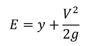
Where:
- E = specific energy [m]
- y = flow depth [m]
- V = flow velocity [m/s]
- g = gravitational acceleration constant [9.81 m/s2]
For a rectangular channel with uniform velocity distribution and width B, the above equation can be expressed in terms of the unit discharge (q) as:
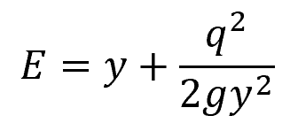
Where:
- q = unit discharge [m2/s]
The unit discharge (q) is the volumetric flow rate per unit width of the channel, as shown in the following equation:
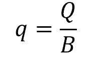
Where:
- Q = volumetric flow rate [m3/s]
- B = width of the channel [m]
Specific Energy Diagram
The specific energy diagram is the plot of the above equation relating the specific energy to the flow depth, as shown below:
For a given unit discharge, the specific energy curve represented by the above equation displays two asymptotes: (E – y) = 0 and y = 0. The former represents a straight line inclined at 45° to the horizontal axis, while the latter represents the horizontal axis. This curve provides insight into various types of flow and their properties, including alternate depths, critical depth, subcritical flow, and supercritical flow.
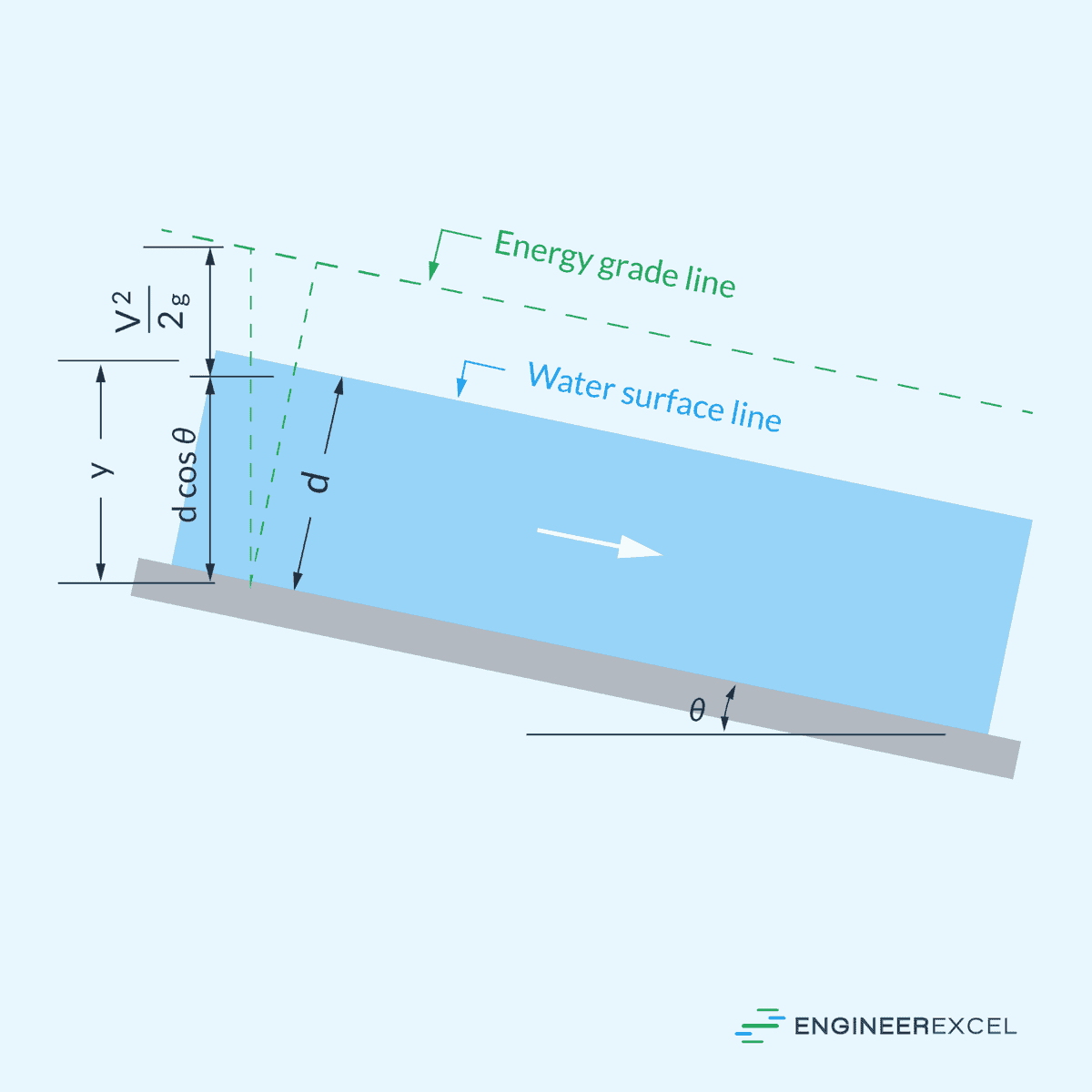
Specific Energy Diagram of Steep Channels
The above equation is generally only applicable to open channels whose bottom slope is not too steep (less than 10%). For channels with steeper bottom slopes, the flow depth measured vertically (y) is different from the depth measured normal to the channel bottom (d), as shown in the diagram below.
In this case, the specific energy equation becomes:
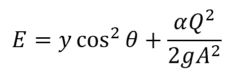
Where:
- θ = angle between the channel bottom and the horizontal axis [rad]
- α = energy coefficient [unitless]
The diagram below shows the specific energy curves for three rates of discharges for a channel having a steep bottom slope.
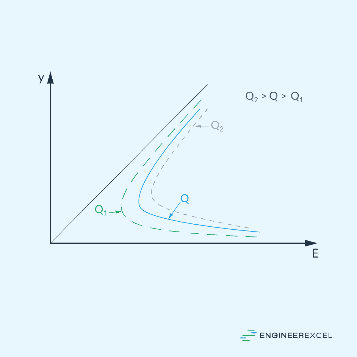
Note that, in the case of steep channels, the angle between the asymptotic straight line and horizontal axis is not 45o. Furthermore, it can be observed that as the discharge rate increases, the specific energy curve shifts to the right.
Specific Energy in Critical Flow Analysis
Determining the Critical Depth
The Specific Energy Diagram is essential in determining the critical depth (yc) of flow in open channels. The critical depth is the point at which critical flow occurs and specific energy is at a minimum for a given flow rate, as shown in the diagram below.
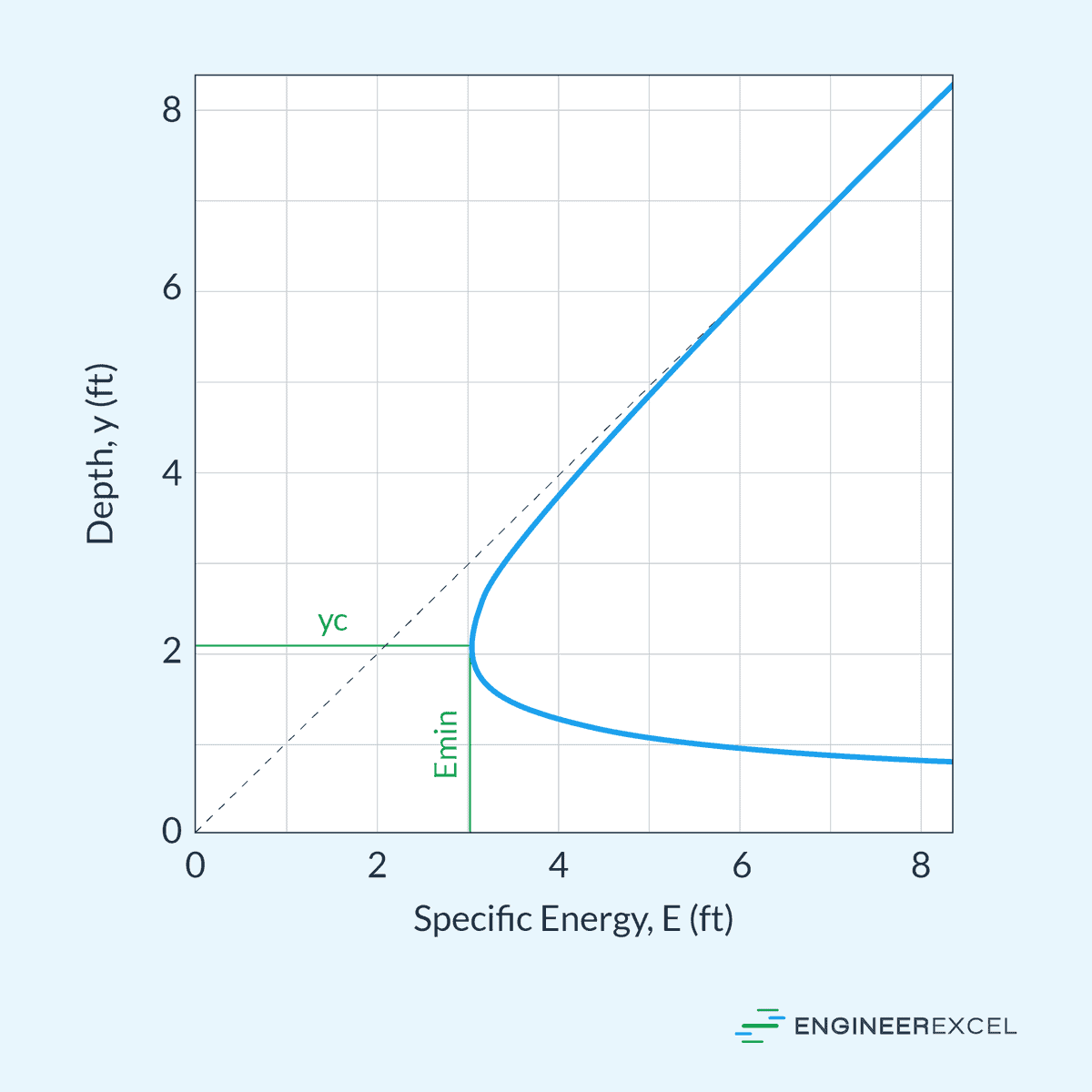
This point separates supercritical flow from subcritical flow. In a specific energy diagram, the flow is considered subcritical on the upper portion of the critical point, where the flow depth is greater than the critical depth. In this regime, the flow is described as tranquil and slow-moving.
On the other hand, supercritical flow refers to the lower portion of the critical point, where the flow depth is less than the critical depth. In this case, the flow is rapid and turbulent.
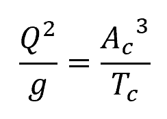
The critical flow condition can be calculated by getting the derivative of the specific energy equation with respect to flow depth, and then equating it to zero. This results to the following equation:
Where:
- Ac = flow area at critical flow conditions [m2]
- Tc = critical width of the channel section at the free surface [m]
The relationship between Ac, Tc, and yc depends on the shape of the channel. For example, for a rectangular channel, the formula for yc can be derived from the above equation as follows:
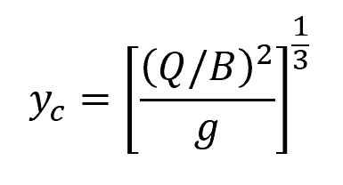
Where:
- B = width of the channel [m]
On the other hand, for a triangular channel, the formula for yc is:
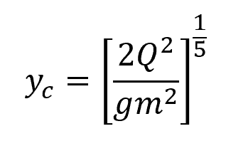
Where:
- m = slope of the triangular channel bed [unitless]
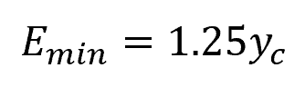
Minimum Specific Energy Calculation
Once the critical depth is found, the minimum specific energy at this depth can be calculated using the following equation:
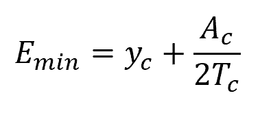
Where:
- Emin = minimum specific energy [m]
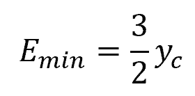
For a rectangular channel, this is equivalent to:
On the other hand, for a triangular channel, this is equivalent to: