
An underflow gate is a control structure designed to regulate the flow of water by allowing excess water to pass beneath, preventing overflow in open channels. It typically works by moving a large plate up and down within guides set in the sides of the channel.
In this article, we will discuss the underflow gate, covering its components, types, flow rate calculation, and applications in various water management systems.
What is an Underflow Gate?
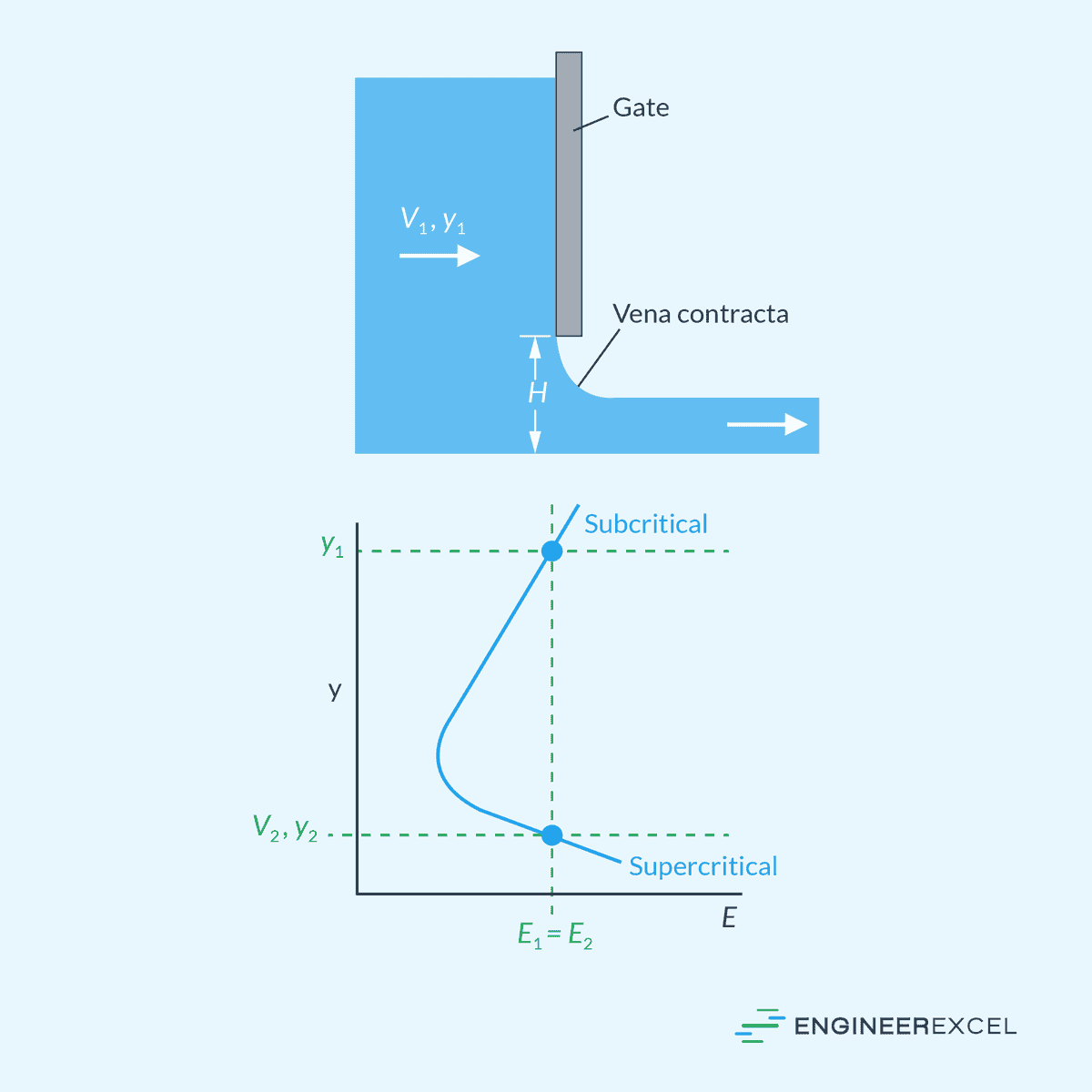
An underflow gate, more commonly known as a sluice gate, is a mechanism designed to control water flow in water management systems. It typically operates by moving a large metal or wooden plate up and down within guides that are set in the sides of an open channel, as shown in the diagram below.

Elevate Your Engineering With Excel
Advance in Excel with engineering-focused training that equips you with the skills to streamline projects and accelerate your career.
The primary function of an underflow gate is to regulate water levels and flow rates in rivers, canals, and reservoirs. Its operation is relatively straightforward— lifting the gate allows water to pass underneath, and lowering the gate restricts the flow of water. When the gate is completely lowered, water may spill over the top, effectively functioning as a weir.
Parts of an Underflow Gate
Underflow gates typically consist of:
- Gate: This is the movable barrier that controls the flow. It can be made of various materials, such as metal or wood.
- Guides: These are vertical structures that contain the gate and provide structural support.
- Mechanism: A manual or powered mechanical system used to lift or lower the gate. This system can be a simple, hand-operated worm drive, or it may be electrically or hydraulically powered.
Types of Underflow Gates
Underflow gates can be categorized into two main types based on their gate movement and usage application: vertical lift gates and radial (Tainter) gates.
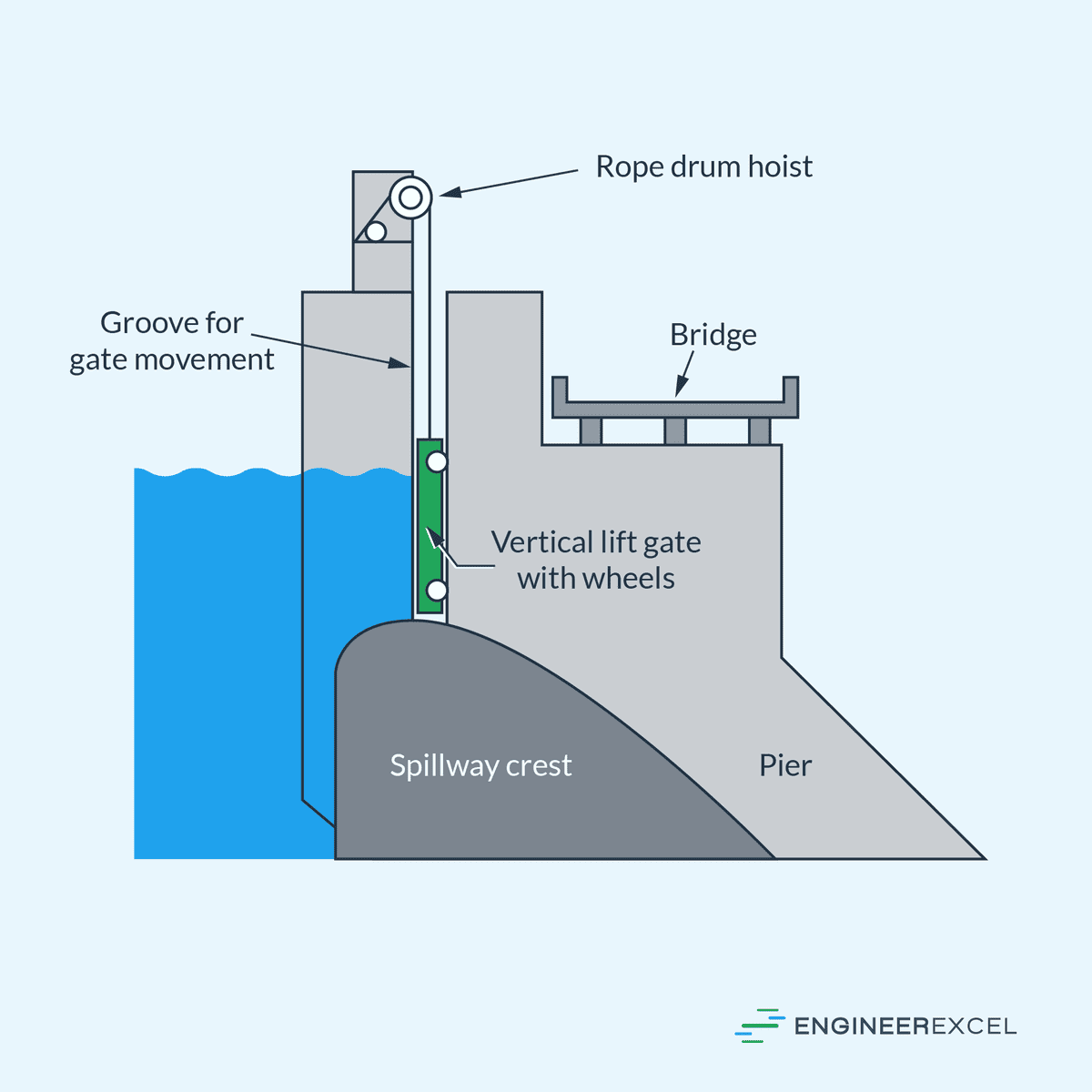
Vertical Lift Underflow Gates
These gates move in a vertical direction and are most common in dam and canal operations. They consist of a solid metal or wooden plate which is lifted or lowered by mechanical means, such as a hoist or screw, to adjust the flow of water.
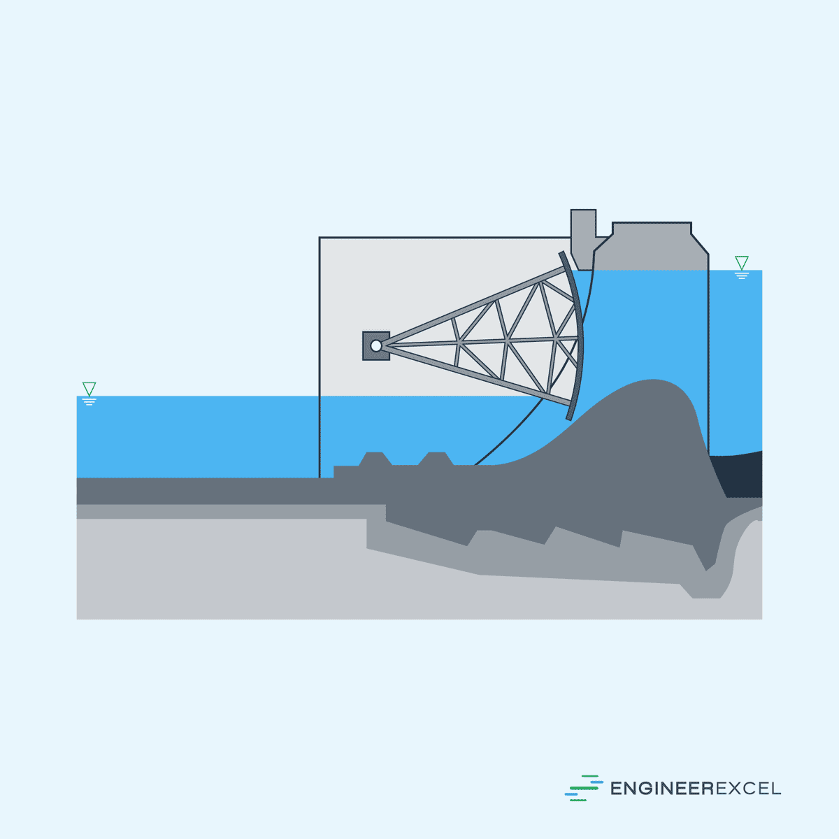
Radial (Tainter) Gates
These gates have a curved structure that pivots around a horizontal axis. The radial design allows for a more efficient distribution of hydrostatic forces, which reduces the required operating force. They are often employed where larger openings are necessary, such as in large-scale flood management systems.
Flow Rate Calculation
When the opening height under an underflow gate is much smaller than the upstream head, the flow can be treated as a square orifice problem. Depending on the downstream head, gate opening, and upstream head, the flow may be categorized as free flow or submerged flow.
Free Flow
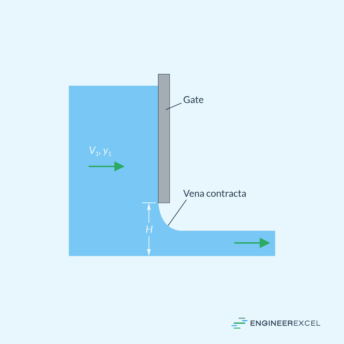
In the case of free flow, the flow is unrestricted and smoothly transitions from subcritical to critical to supercritical as it passes through the gap, similar to a converging-diverging nozzle in gas dynamics. Friction can be disregarded in this scenario, and the specific energy remains constant between the upstream and downstream sections, as shown in the diagram below.
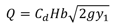
The free discharge contracts to a depth approximately 40% less than the gate’s gap height. Since the flow resembles a free orifice discharge, the flow rate can be approximated using orifice theory:
Where:
- Q = flow rate [m3/s]
- Cd = discharge coefficient [unitless]
- H = height of the gate gap [m]
- b = width of the gap [m]
- g = gravitational acceleration [9.81 m/s2]
- y1 = depth of the subcritical upstream flow [m]
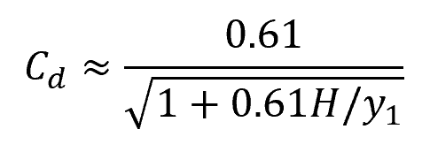
For H/y1 ratios less than 0.5, the discharge coefficient can be approximated as:
Submerged Flow
When the tailwater is high, free discharge is not achievable. In this case, the underflow gate is considered drowned or partially drowned. This leads to energy dissipation in the exit flow, likely resulting in a drowned hydraulic jump, as shown in the diagram below.
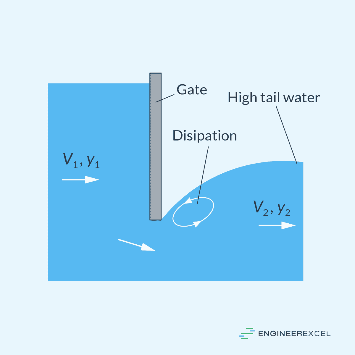
After the energy is dissipated, the downstream flow will revert to a subcritical state. The flow rate equations used for free flow are not applicable in this scenario, and it is essential to rely on experimental discharge correlations.
Applications of Underflow Gates
Underflow gates play an important role in modern water management systems, facilitating the regulation and control of water flow for specific purposes.
Irrigation Infrastructure
Irrigation systems rely on underflow gates to manage the distribution of water to agricultural fields. Farmers and water managers can adjust these gates to vary the flow rate, ensuring that crops receive the necessary amount of water throughout various stages of growth. This adjustability is critical for conserving water and promoting efficient use of resources.
Flood Control Systems
Underflow gates are integral components in flood control, deployed to divert excess water away from populated or agricultural areas to pre-designed floodways or detention basins. Engineers design these systems to withstand and control water levels during peak flow conditions. For instance, a retention basin gate might be engineered to open once the upstream water level reaches a certain threshold.
Industrial Water Management
In the industrial sector, underflow gates are used to control and measure the flow of water for cooling processes, waste management, and water treatment facilities. The precision of such gates enables fine control over water levels and flow rates, which is essential for maintaining optimal industrial operations.
Hydropower Generation
In hydropower plants, underflow gates play a role in controlling the release of water to turbines, managing the generation of electrical power.