
FEATURED BEAM DESIGN RESOURCES
[no_toc]

Overhanging Beam: Analysis, Design, and Practical Applications
Shear Force: Understanding its Impact on Structural Integrity
Shear and Moment Diagram: Guide for Engineering Analysis
Point Loads: Understanding the Mechanics
Fixed Beams: Analysis and Engineering Applications
Bending Moment Diagram: Essential Guide for Engineers
Shear Diagram and its Role in Beam Design

Transverse Shear Stress: Analysis and Calculation
Understanding Distributed Load in Beam Design

Yielding Moment
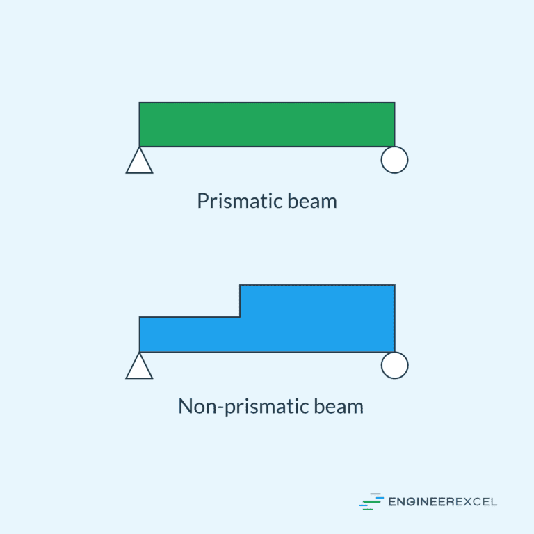
Prismatic Beams: Key Fundamentals and Design
Understanding Shear Stress Distribution in Beam Analysis
Continuous Beams: Characteristics, Applications, and Analysis

Cantilever Beam: A Comprehensive Overview
Shear Center: Understanding its Concept in Beam Design
Beams are structural elements that bear loads and distribute them horizontally to support buildings and other structures. Properly designing beams is important to ensure they can withstand the applied loads, preventing structural failures and ensuring the overall stability and safety of the construction.

In this article, we will discuss the essential principles of beam design, including the types of beams, the different beam loading configurations, and the analysis of internal forces within the beams.
Introduction to Beam Design

Elevate Your Engineering With Excel
Advance in Excel with engineering-focused training that equips you with the skills to streamline projects and accelerate your career.
Beams are essential structural elements that provide support for loads and resist bending. Typically positioned horizontally between supports, they play an important role in the construction of buildings, bridges, and various other structures.
The design of beams is on the basis of strength to withstand the internal shear and moment developed along their length. While some beams may also experience axial forces, these are often disregarded in the design process due to their relatively minor impact compared to shear and bending stresses.
The beam design process typically begins with material selection, followed by the calculation of the maximum internal shear and moment along the beam’s length. By considering the allowable stress of the chosen material and the expected maximum shear and moment, the appropriate size and geometry of the beam capable of handling the load can be established.
In addition to strength considerations, beams must be adequately braced along their sides to prevent buckling or sudden instability. Furthermore, in certain cases, beams must be designed to limit deflection, particularly when supporting ceilings made of brittle materials like plaster.
Beam design encompasses numerous factors that require careful consideration. This article offers a comprehensive overview of the key concepts involved in beam design.
Beam Types
Beams can be classified based on their support configuration, which refers to how the beam is supported at its ends. The support conditions significantly affect the behavior of the beam under different loading conditions. The common types of support configurations for beams include simply supported beam, overhanging beam, cantilever beam, continuous beam, and fixed beam.
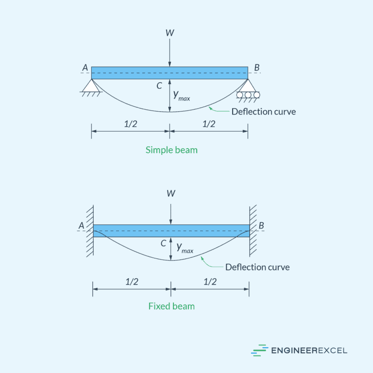
Simply Supported Beam
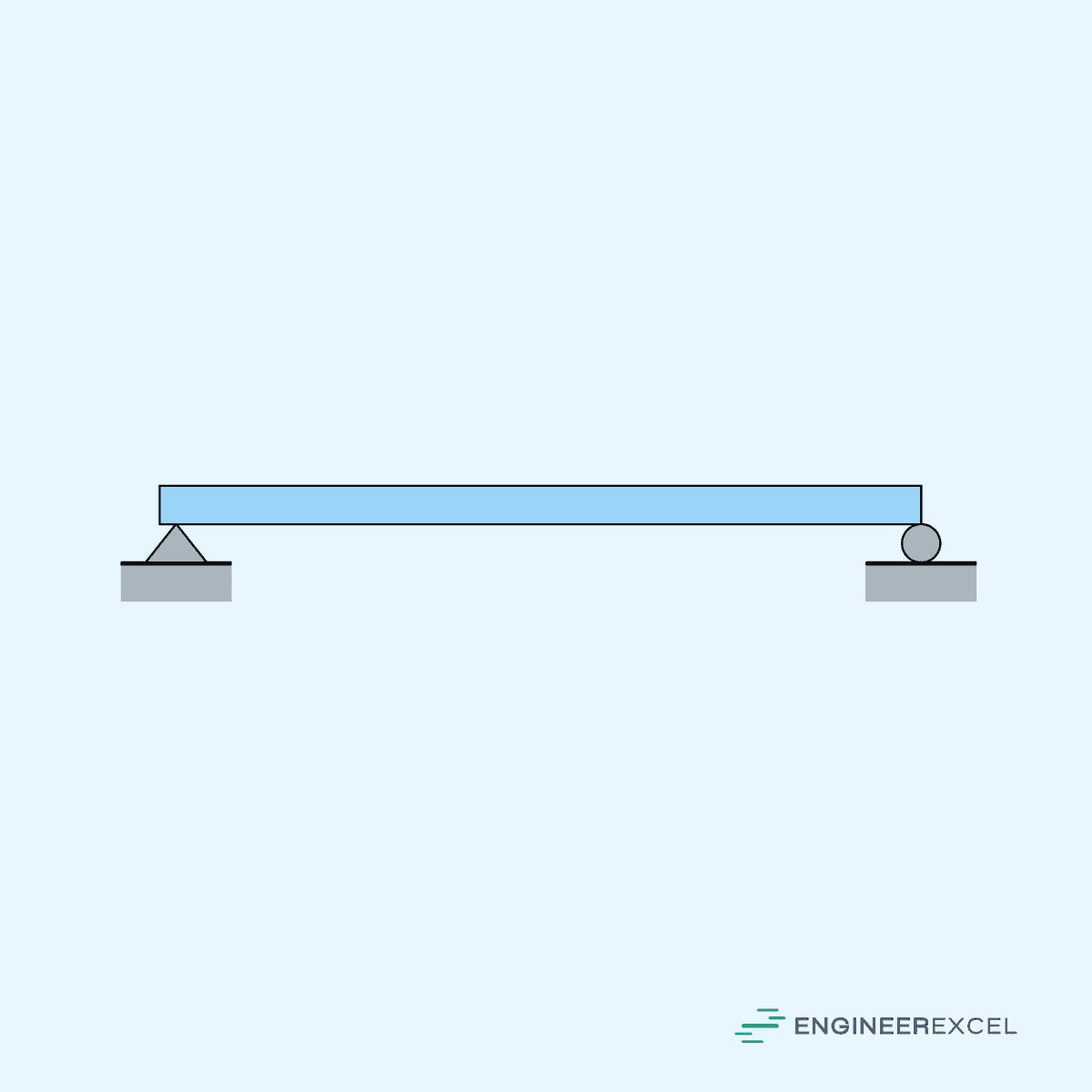
A simply supported beam is a type of beam that is supported at both ends, typically by a hinge and a roller. The reactions at these supports can be either vertical or horizontal, but they cannot provide any rotational stiffness. This type of beam is commonly used in simple structures due to its ease of analysis.
Overhanging Beam
An overhanging beam has one or more sections that extend beyond one or both of its supports. It’s common in architectural designs where cantilevered balconies or roof eaves are required. Overhanging beams have more complex stress distributions and require more detailed analysis than simply supported beams.

Cantilever Beam
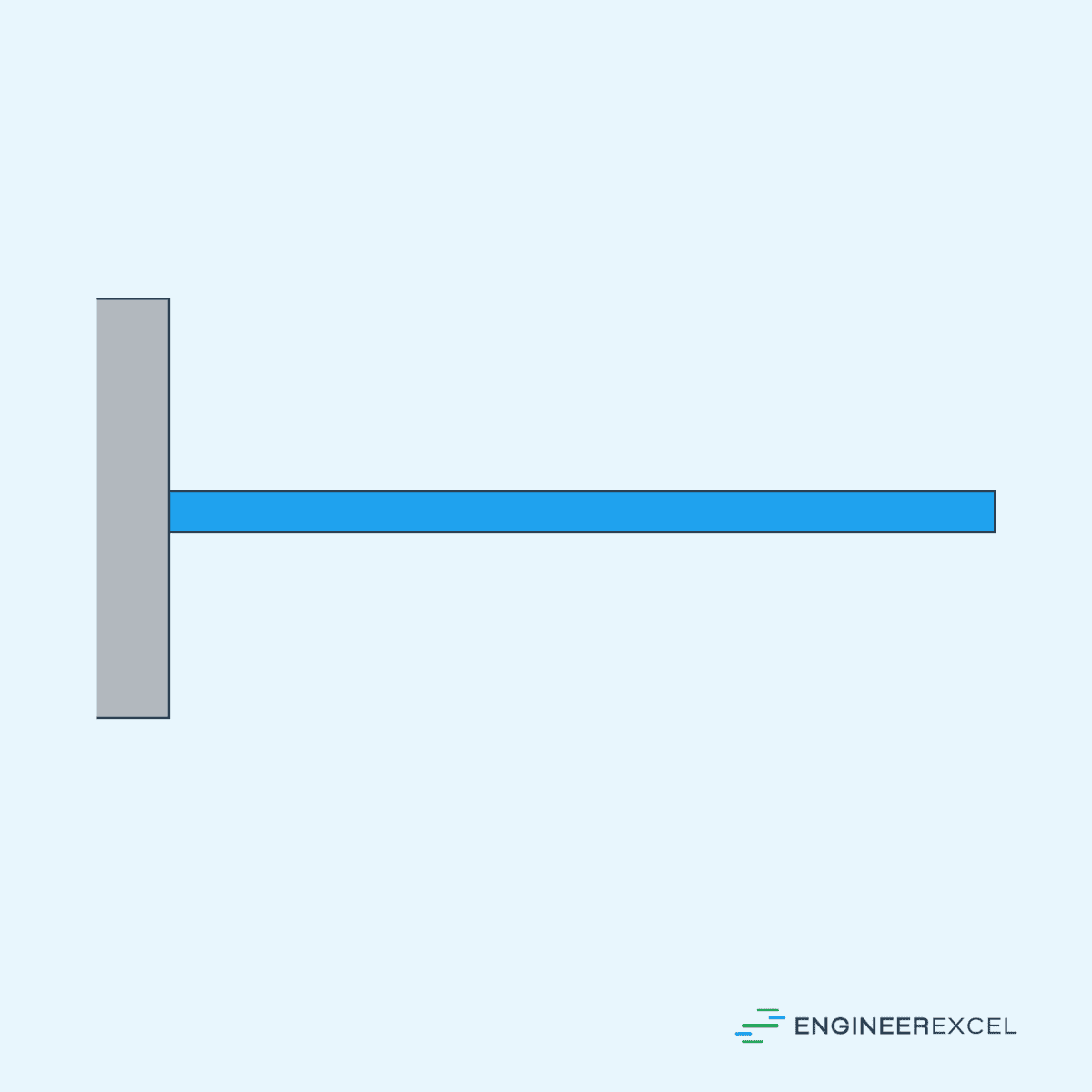
A cantilever beam is a type of beam that is fixed at one end and free at the other. It is commonly used in applications where a projection without any visible support is required, such as shelves or balconies. The load on a cantilever beam generates both bending moment and shear force that need to be considered during the design process.
Continuous Beam
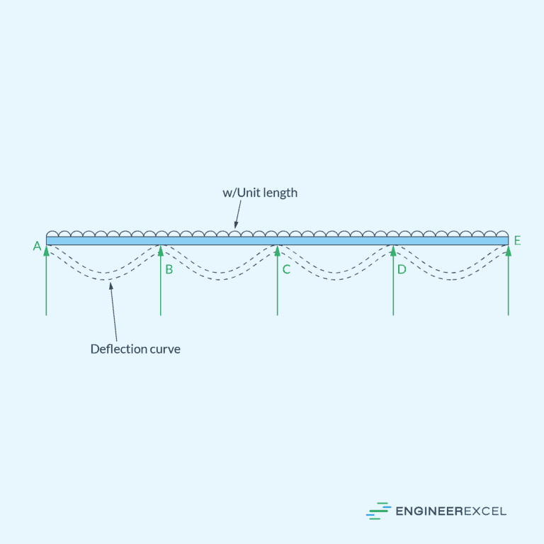
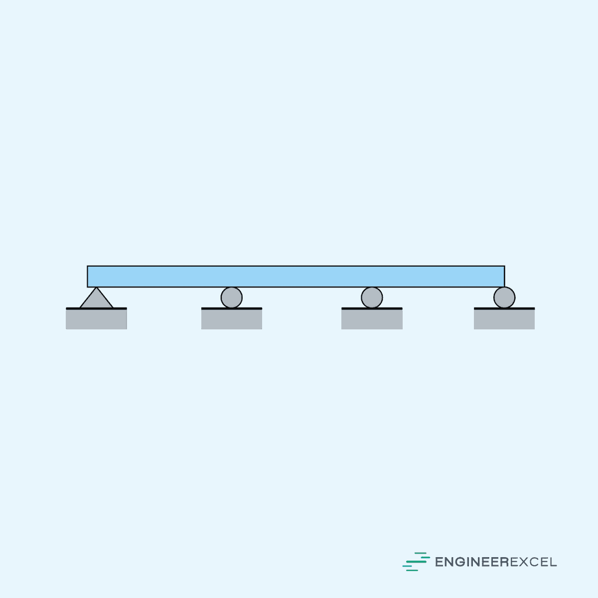
A continuous beam is a beam that spans over more than two support points. In this case, the beam is subjected to internal moments and shear forces at multiple locations. Continuous beams are typically found in multi-span bridges, buildings, or floor systems.
Fixed Beam
A fixed beam is a beam that is rigidly connected to its supports at both ends. It is more resistant to deflections and rotations compared to simply supported beams, making it more suitable for applications requiring high rigidity. However, fixed beams are more challenging to analyze due to the presence of both bending moment and shear force at the supports.

Beam Loading Configurations
When designing a beam, it is essential to understand the different types of loads that can be applied to it. Beam loading configurations can be broadly categorized into two types: point load and distributed load.
Point Load
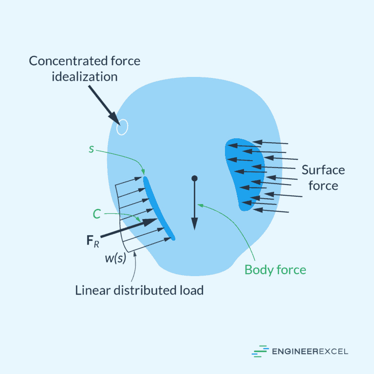
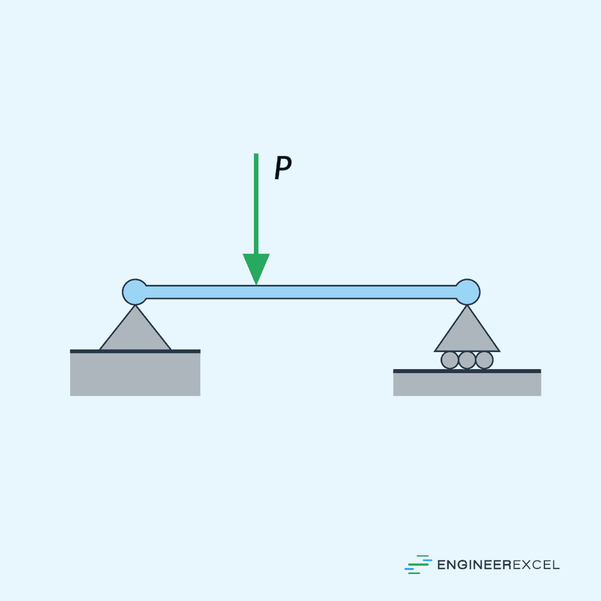
A point load, also known as a concentrated load, is a load that acts on a specific point or location along the beam. These loads significantly concentrate the forces on the beam, causing high stress and deflection in the surrounding area. Some examples of point loads include the weight of a column on a supporting beam or a load applied by crane.
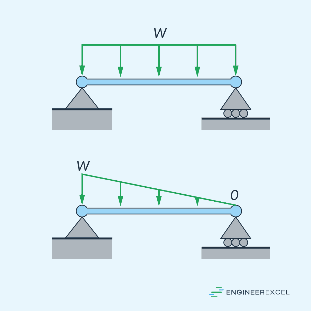
Distributed Load
A distributed load is a load that is spread over a certain length of the beam. Two common types of distributed load are uniformly distributed loads (UDL), where the load intensity remains constant throughout the span, and triangular distributed loads where the load intensity varies linearly over the span.
Internal Forces in Beams
When analyzing beams, understanding the internal forces is important for predicting the responses within the structure. These forces include shear force and bending moments.
Internal Shear Force
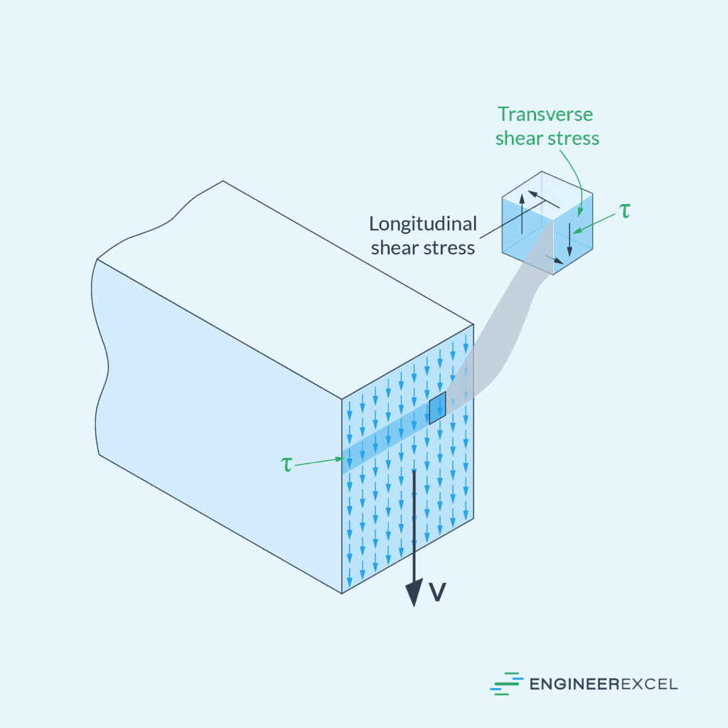
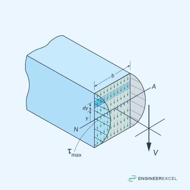
Internal shear force refers to the force that acts parallel to the cross-section of a beam. It arises due to external loads applied perpendicular to the axis of the beam.
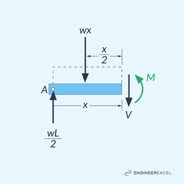
Shear force varies along the beam’s length due to varying load conditions. To calculate the shear force at a specific point, the beam is imagined to be cut into two segments, and then equilibrium equations are applied to maintain internal stability.
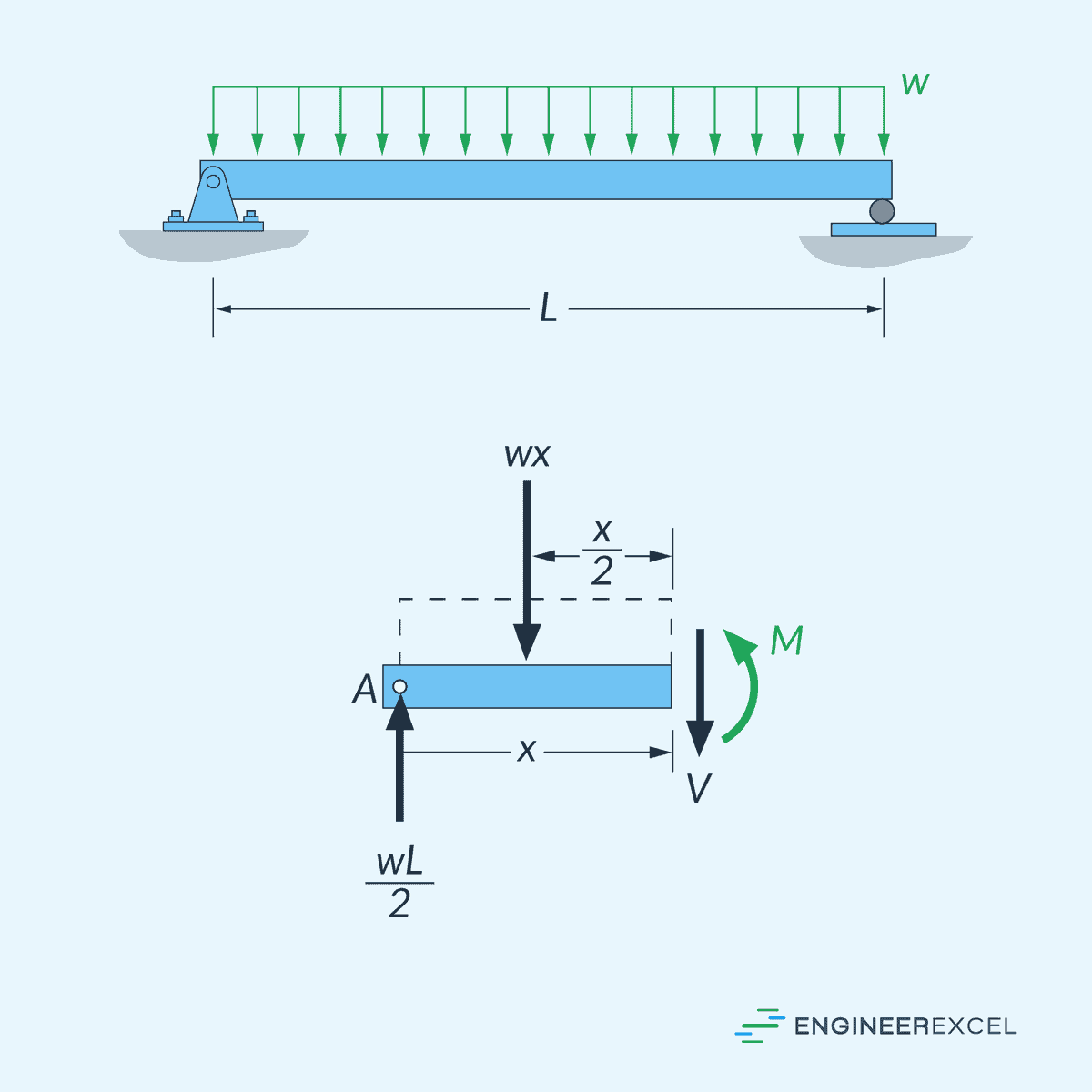
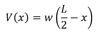
For example, for a simply supported beam subjected to a uniformly distributed load (w), shown above, shear force at any point x from one end can be calculated as:
Where:
- V(x) = shear force at any point x from one end [N]
- x = distance of the point of interest from the end support [m]
- w = uniformly distributed load [N/m]
- L = total length of the beam [m]
Bending Moment
A bending moment occurs when a transverse force or a moment acts on the beam, causing it to bend. The resulting internal stress in the beam causes the material to resist deformation, leading to the bending moment.
Similar to shear force, bending moments can be determined by evaluating equilibrium equations. The bending moment at any point x is calculated by taking the sum of bending moments caused by loads and reactions acting on the beam to the left or right of the point.
For example, for a simply supported beam subjected to a uniformly distributed load (w), shown above, bending moment at any point x from one end can be calculated as:
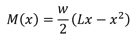
Where:
- M(x) = bending moment at any point x from one end [N]
Shear and Moment Diagrams
In beam design, it is important to know the shear force and bending moment in each segment of the beam for accurate structural analysis. One of the ways to do this is through the use of shear and moment diagrams.
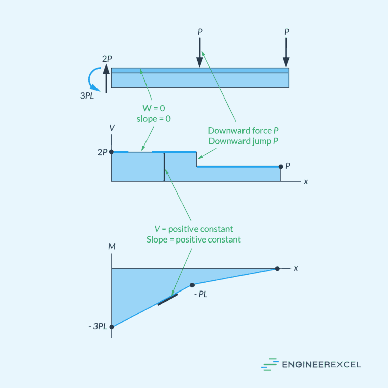
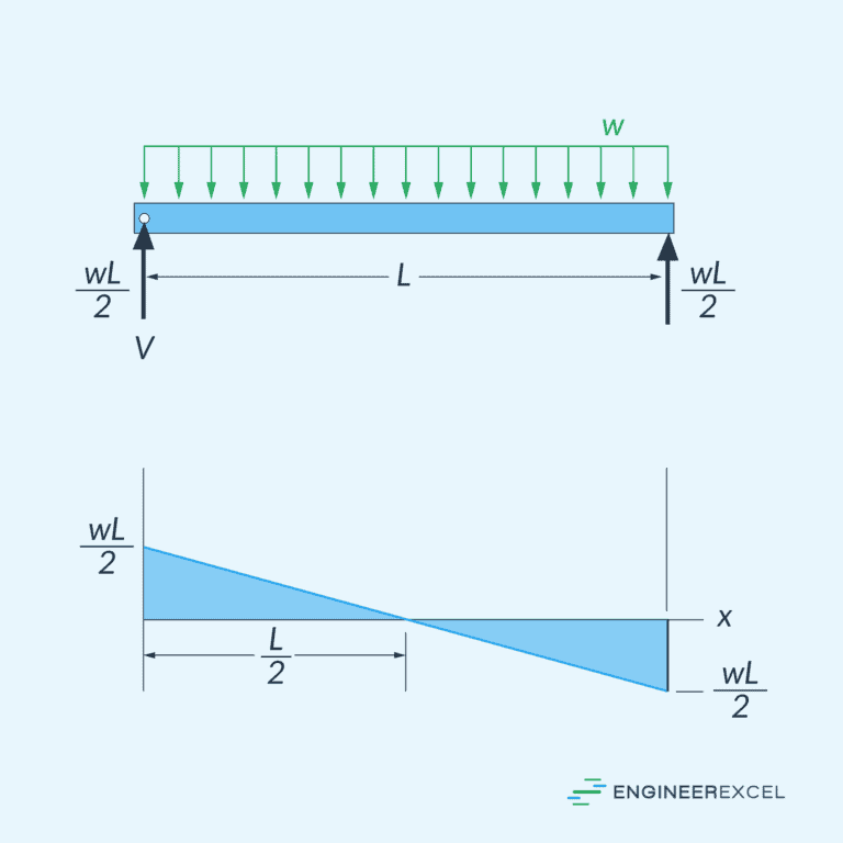
Shear and moment diagrams are graphical representations used to illustrate the variation of internal forces along the length of a beam. The shear diagram shows how the internal shear force changes at different locations along the beam, while the moment diagram illustrates the variation in internal bending moments.
The horizontal axis normally represents the length of the beam, while the vertical axis represents the magnitude and direction of the shear and bending moment.
For example, using the equations for the shear (V) and bending moment (M) obtained above for a simply supported beam subjected to a uniformly distributed load, the shear and moment diagrams can be plotted as follows:
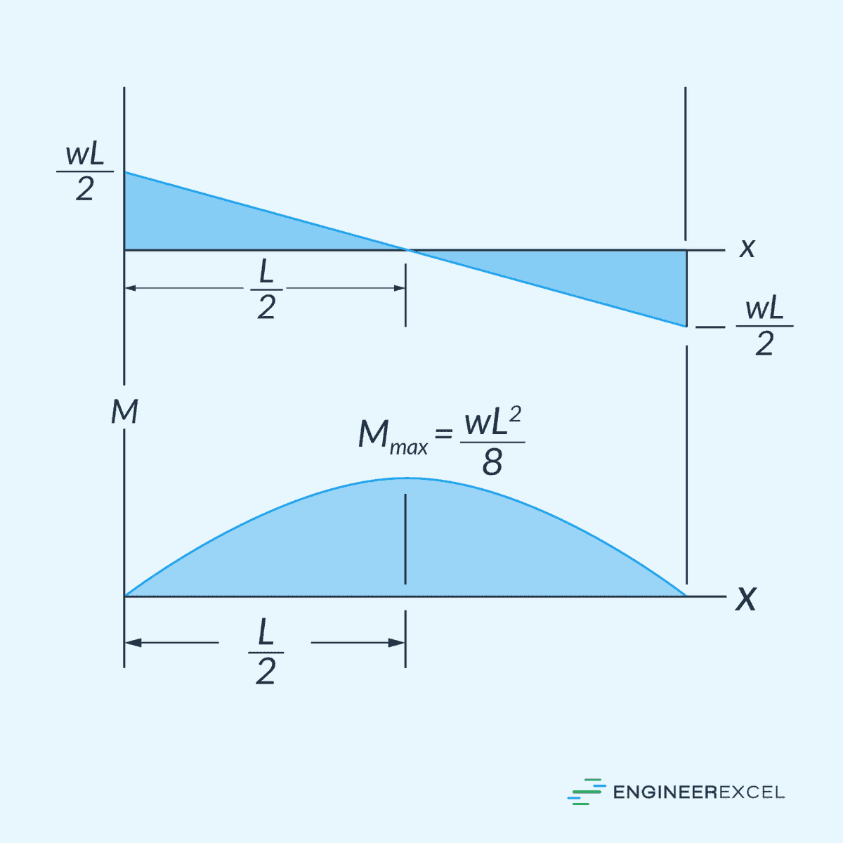
By plotting the shear and moment diagrams, you can pinpoint critical locations that may require additional reinforcement or consideration in the design process. By assessing these vulnerable points, engineers can optimize the structural design to ensure that the beam can effectively support applied loads without compromising safety or structural integrity.