
Shear force refers to the internal force developed within a body to counteract external loads that try to cause two segments to slide over one another. In engineering, understanding shear force is important for analyzing and designing structures, as high shear stresses can result to material failure.

In this article, we will discuss the concept of shear force and its calculations.
Understanding Shear Force
Forces can be categorized as acting either internally or externally within a body. External forces are applied from outside the body and cause it to deform or move, whereas internal forces are developed to counteract external forces and maintain the structure’s stability.
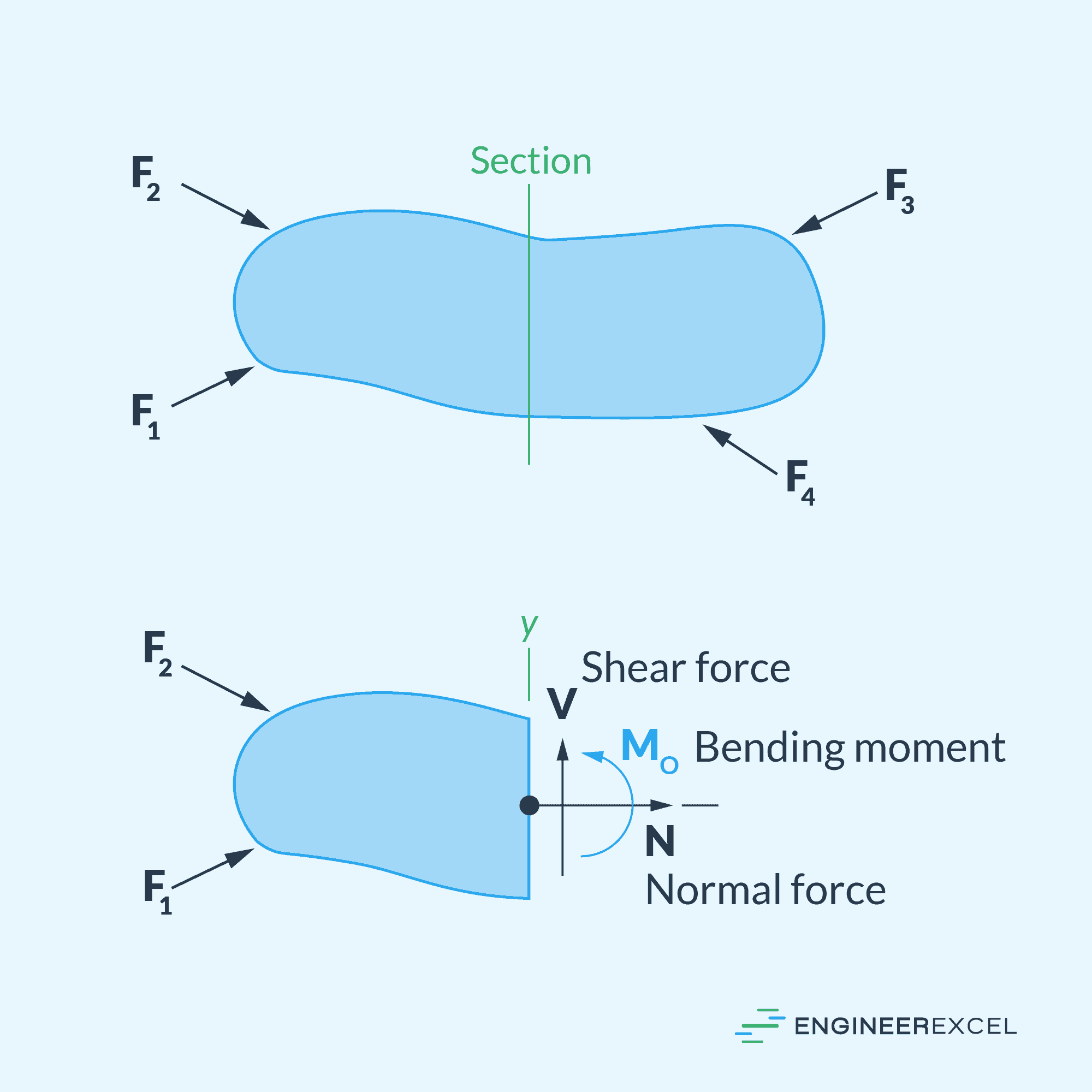
Shear force, often denoted as V, is a type of internal force that acts within a body when external loads try to cause two segments to slide over one another, as shown in the diagram below. It lies in the plane of the area under consideration and is developed as a result of the applied forces.

Elevate Your Engineering With Excel
Advance in Excel with engineering-focused training that equips you with the skills to streamline projects and accelerate your career.
In engineering, this concept is essential for analyzing and designing structures, such as beams, plates, and shafts, as failure of these components due to high shear forces can lead to catastrophic consequences.
To better understand shear force, it is important to know the concept of stress and strain. Stress is generally defined as force acting per unit area in a material, whereas strain is the deformation or change in shape that occurs as a result of applying stress.
Shear stress, in specific, can be described as the stress component that acts parallel to the internal surfaces of the material being subjected to shear forces. Shear strain, on the other hand, corresponds to the change in shape or angular deformation of the material due to the applied shear forces. Hence, shear force is responsible for generating shear stresses that ultimately lead to deformation in the material.
In some instances, continuous exposure to high shear forces can cause the material to fail or even fracture. Therefore, it is important for engineers to analyze the shear force in a structure and ensure that it is within acceptable limits to prevent failure.
Shear Force Calculations
The first step in calculating shear forces is to determine the external forces and reactions acting on the structure. This is commonly done by applying equilibrium equations for a given system— that is, summation of forces and moments in different directions. Once all the external forces and reactions are known, the internal shear force at any section can be found by performing a free-body diagram (FBD) of a segment and reapplying equilibrium equations.
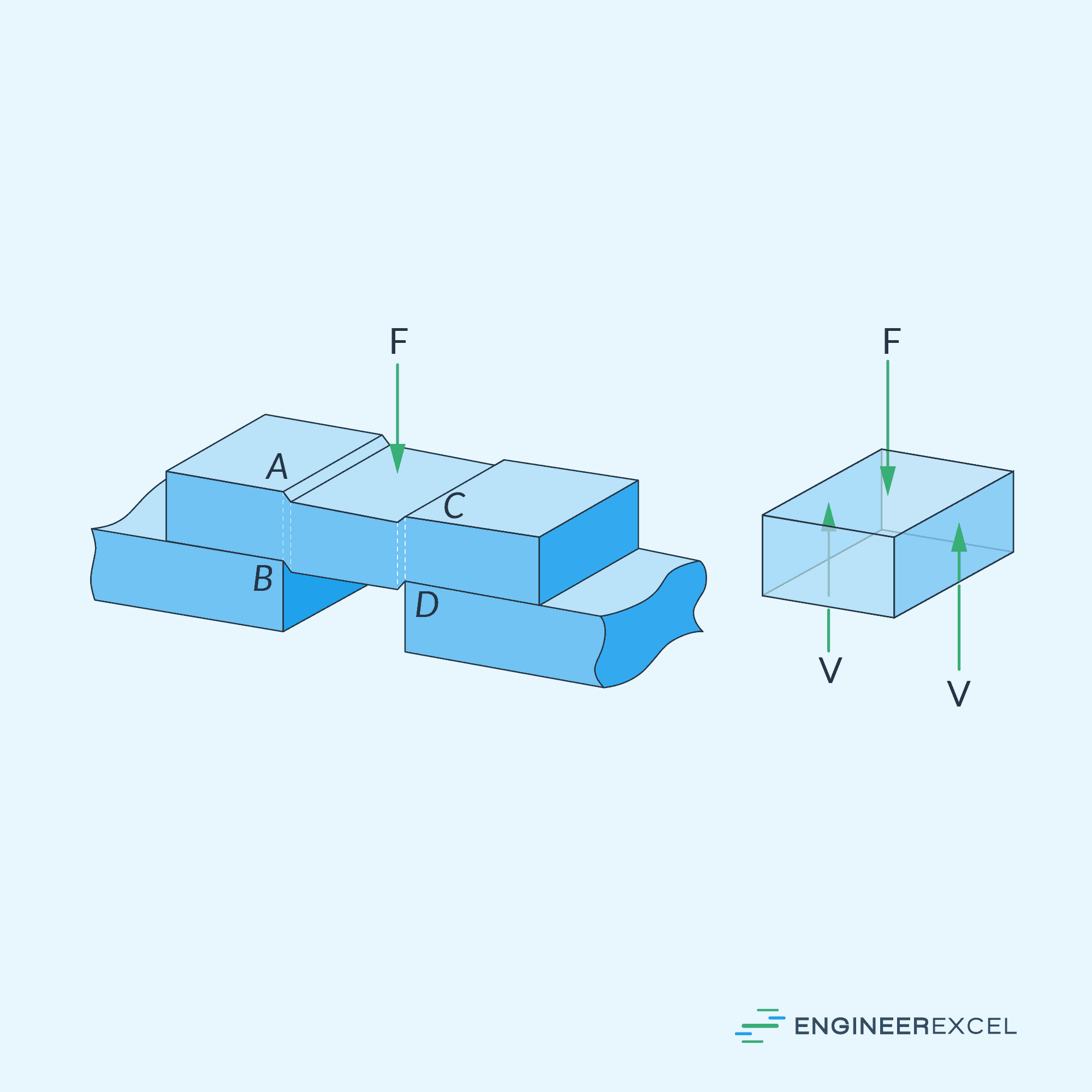
For example, in the figure above, the internal shear force can be calculated by equating the summation of vertical forces to zero, such that:
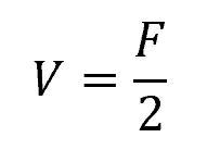
Where:
- V = internal shear force [N]
- F = applied load [N]
Average Shear Stress
Once the internal shear force is known, the average shear stress on the cross-sectional area can be calculated using the following formula:
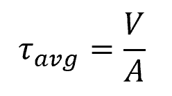
Where:
- τavg = average shear stress [Pa]
- A = area of the cross-section [m2]
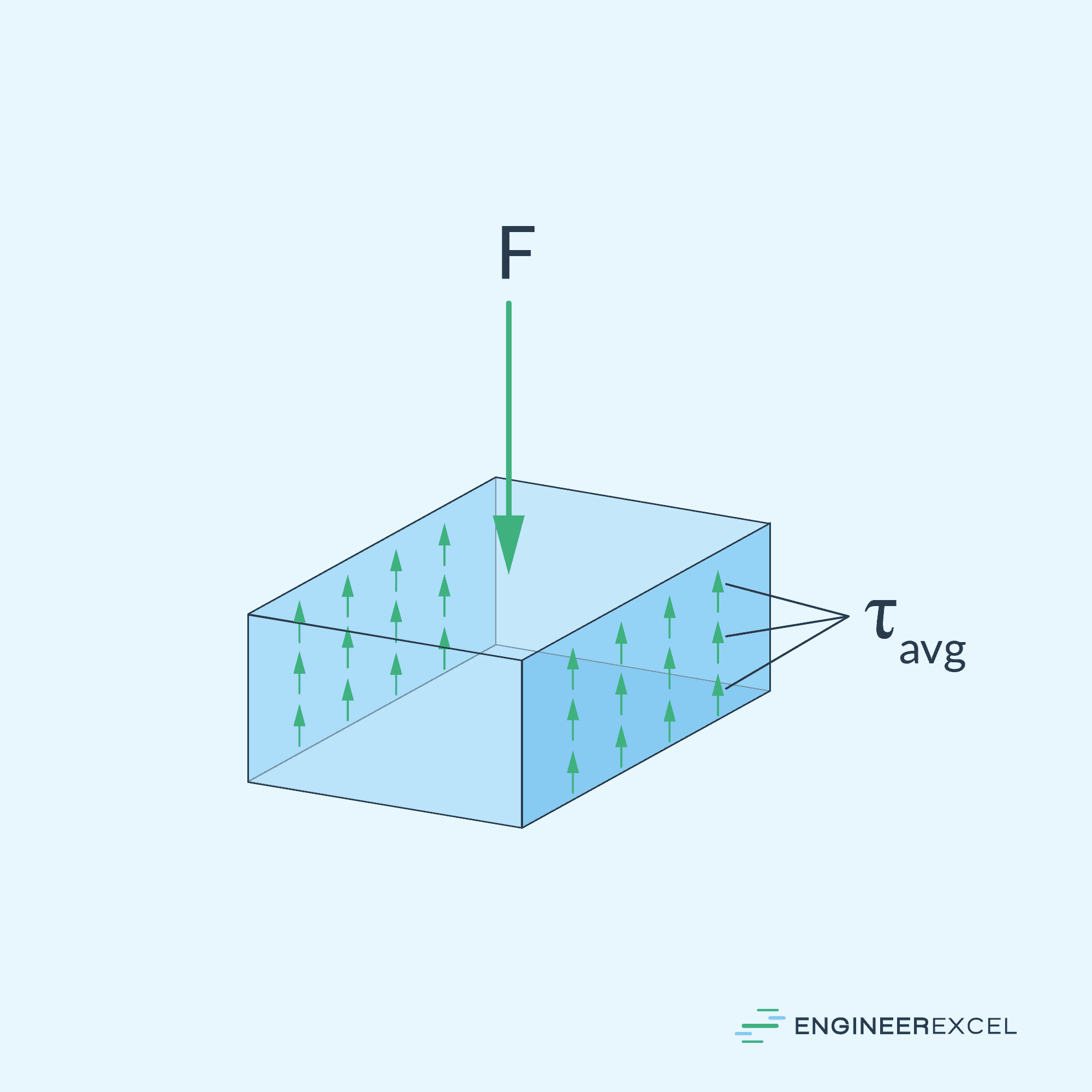
The above formula assumes that shear stress is uniform across the cross-section, as shown in the diagram above. However, in reality, shear stress varies non-linearly, with the intensity varying from zero at the top and bottom to a maximum value at the neutral axis.
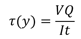
The Shear Formula
A more accurate representation of the shear stress distribution can be obtained using the shear formula as follows:
Where:
- τ(y) = shear stress at distance y from the neutral axis [Pa]
- V = internal shear force [N]
- Q = first moment of area between the segment of interest and the neutral axis [m3]
- I = moment of inertia of the entire cross-section [m4]
- t = width of the cross-sectional area at the point where shear stress is to be determined [m]
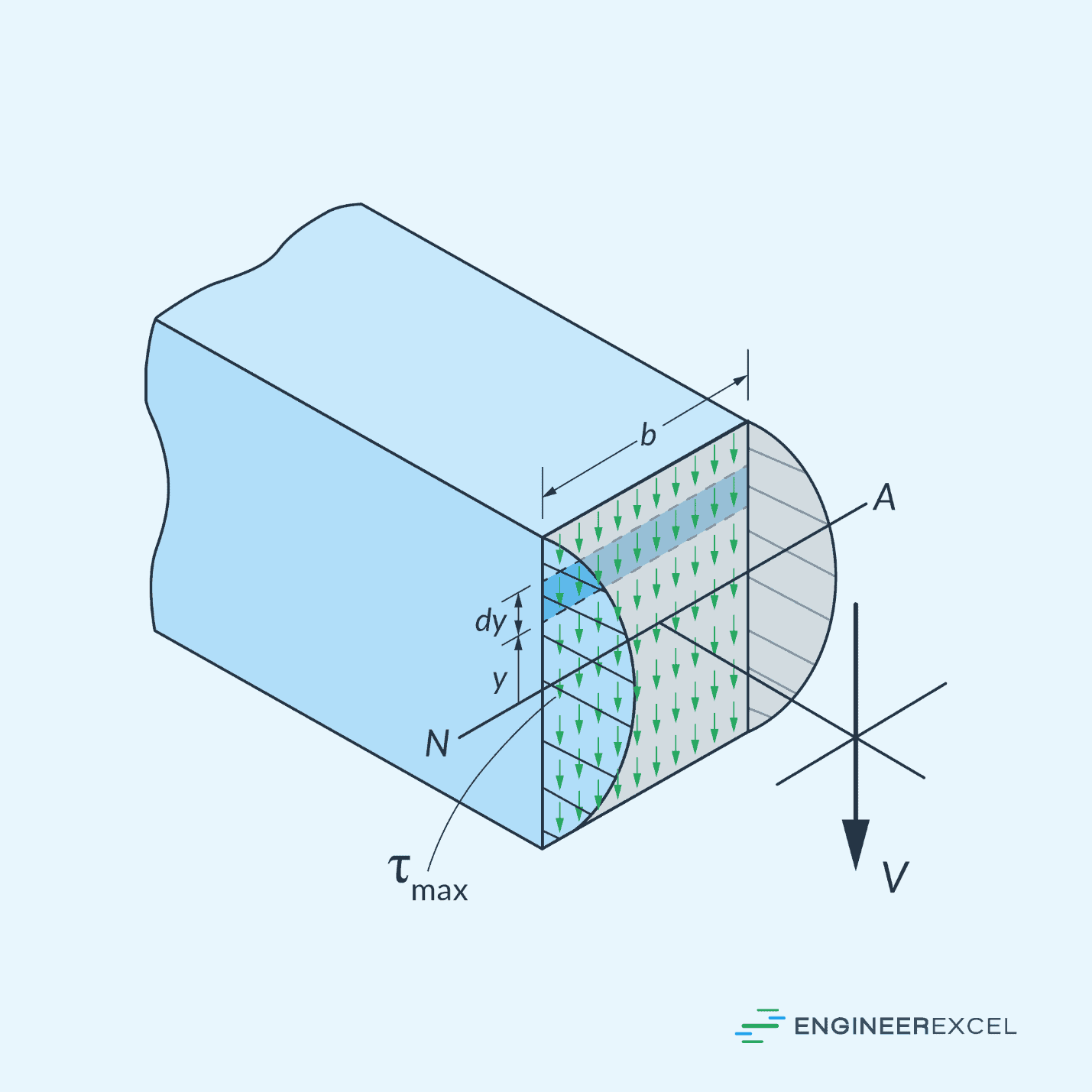
It’s important to consider the shape of the cross-section when calculating shear stress. Different shapes result in varying shear stress distribution and maximum values. For example, a rectangular cross-section has a parabolic distribution, as shown in the diagram above, while an I-beam has different expressions for the flange and web regions.