
An overhanging beam is a type of beam that extends beyond one or both of its supports, creating an overhang. This configuration can be found in bridges, balconies, roof structures, and shelves and storage systems.

In this article, we will cover overhanging beams, their practical applications, and the calculations involved.
What is an Overhanging Beam?
Beams are structural elements primarily designed to resist loads applied laterally to the beam’s axis. They are essential in engineering and construction, providing support to floors, roofs, and other structures to bear loads. They can be made of various materials, such as wood, steel, or reinforced concrete.
Beams are typically classified according to their support conditions, which are the points where the beam’s weight is carried by other elements. This article focuses on one type called the overhanging beam.

Elevate Your Engineering With Excel
Advance in Excel with engineering-focused training that equips you with the skills to streamline projects and accelerate your career.
An overhanging beam is a type of beam that extends beyond one or both of its supports. This additional length of the beam that projects beyond the support creates an overhang, giving the beam its name.
In most cases, the support consists of a pin and a roller support. The pin support prevents the attached point of the beam from moving, but allows for rotation. On the other hand, the roller support allows movement parallel to the beam axis and only restricts transverse displacement.
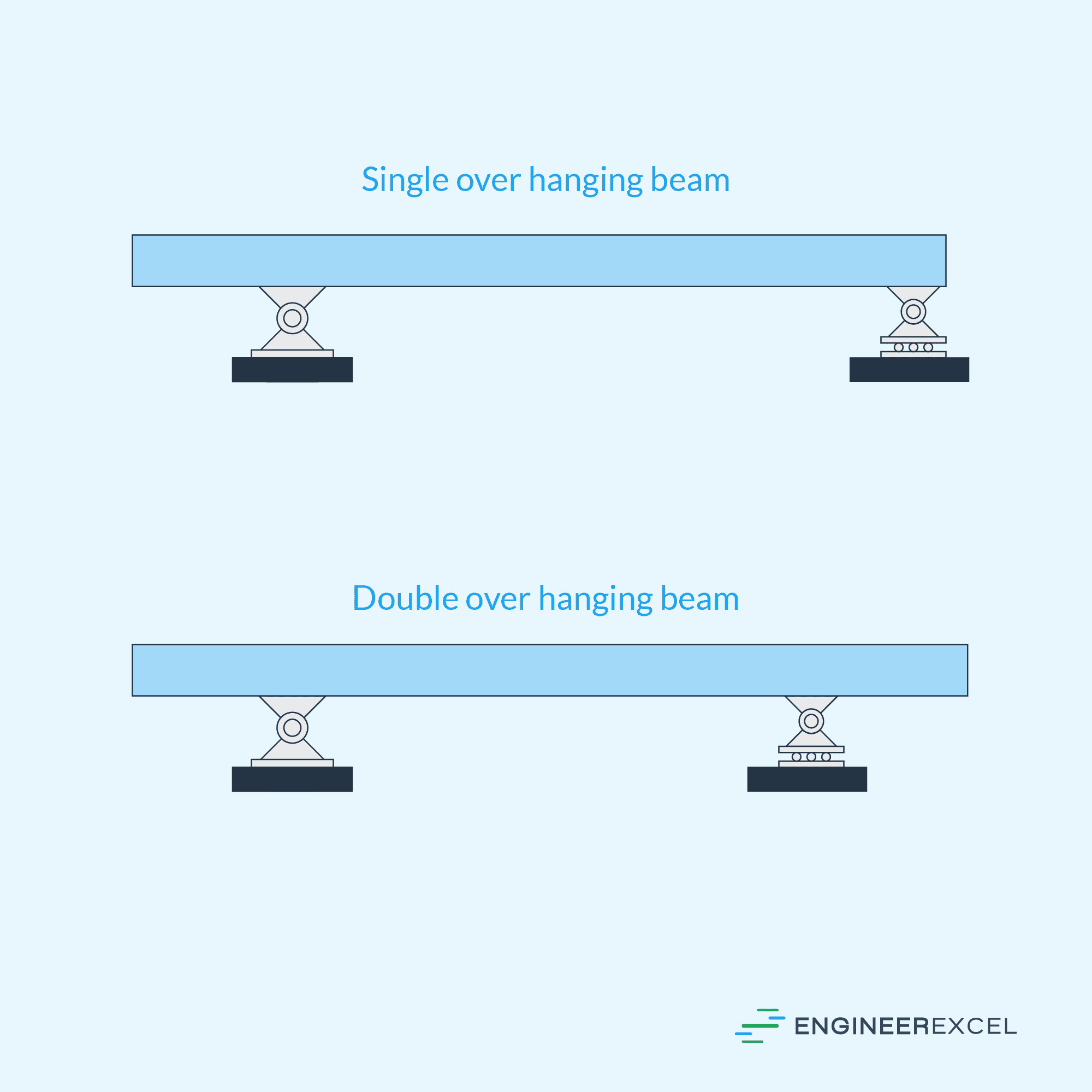
The overhang or extended length can exist on one side in the case of a single overhanging beam or on both sides in the case of a double overhanging beam, depending on the design and function of the structure it is part of. These configurations are illustrated in the diagram below.
Applications of Overhanging Beams
Overhanging beams are found in various applications in engineering and construction such as:
- Bridges: In some designs, overhanging beams are used in the construction of bridges, where the main beam spanning between supports may have additional overhangs to accommodate walkways or other features.
- Balconies: Overhanging beams can be used to support cantilevered balconies on buildings, allowing for extra space without the need for additional vertical supports.
- Roof structures: In some architectural styles, overhanging beams are employed to create eaves or extended rooflines, providing shading or weather protection.
- Shelves and storage systems: In industrial and warehouse applications, overhanging beams may be used to create extended storage areas without the need for additional columns or supports.
Although the overhanging beam has some advantages, like flexibility in design and efficient use of materials, proper care must be taken when designing and implementing such beams. Engineers and architects need to ensure that the structure’s support system can safely bear the additional stresses resulting from the overhanging portions of the beam and that the required deflection and strength limits are met.
With proper planning and understanding of the project’s requirements, overhanging beams can be a valuable addition to various engineering and construction applications, providing both aesthetic and functional benefits.
Overhanging Beam Sample Calculations
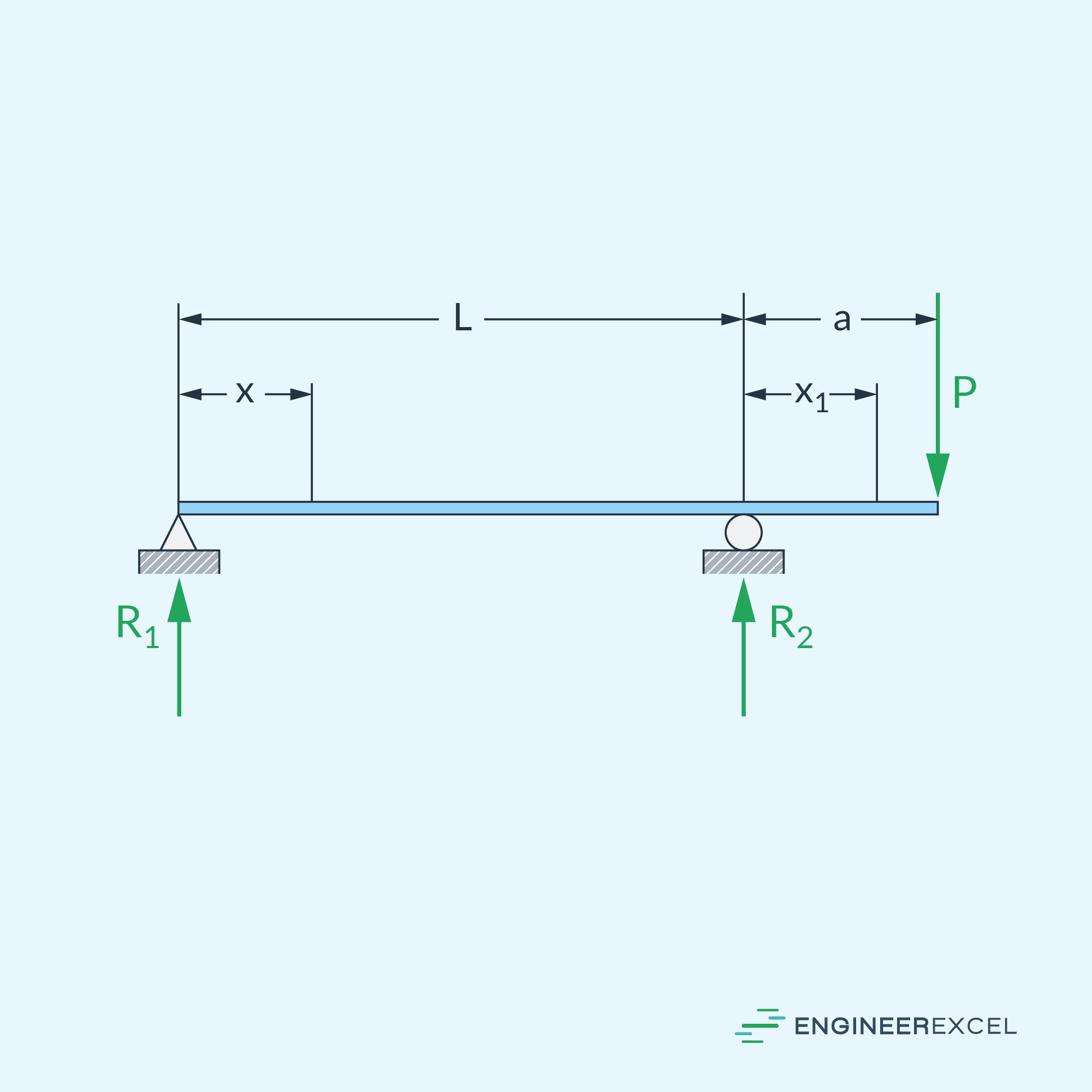
The first step in designing an overhanging beam is to calculate the reactions at the supports. To give an example, consider the diagram of an overhanging beam subjected to a point load located at the end of its overhang This is shown in the diagram below.
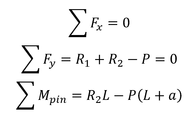
The reaction forces at the supports can be determined by applying the equilibrium equations of statics for force and moment, such that:
Where:
- Fx = horizontal forces [N]
- Fy = vertical forces [N]
- Mpin = bending moments about the pin support [N-m]
- R1 = vertical reaction force at the pin support [N]
- R2 = vertical reaction force at the roller support [N]
- P = applied point load [N]
- L = length between the supports [m]
- a = length of the overhang [m]
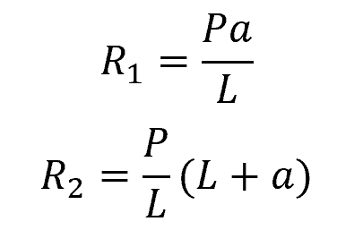
There are two equations above with two unknowns. Hence, the reaction forces can be calculated as follows:
Once the reactions are calculated, the shear force (V) and bending moment (M) distributions along the beam can be determined. These would be represented through shear and bending moment diagrams, shown below.
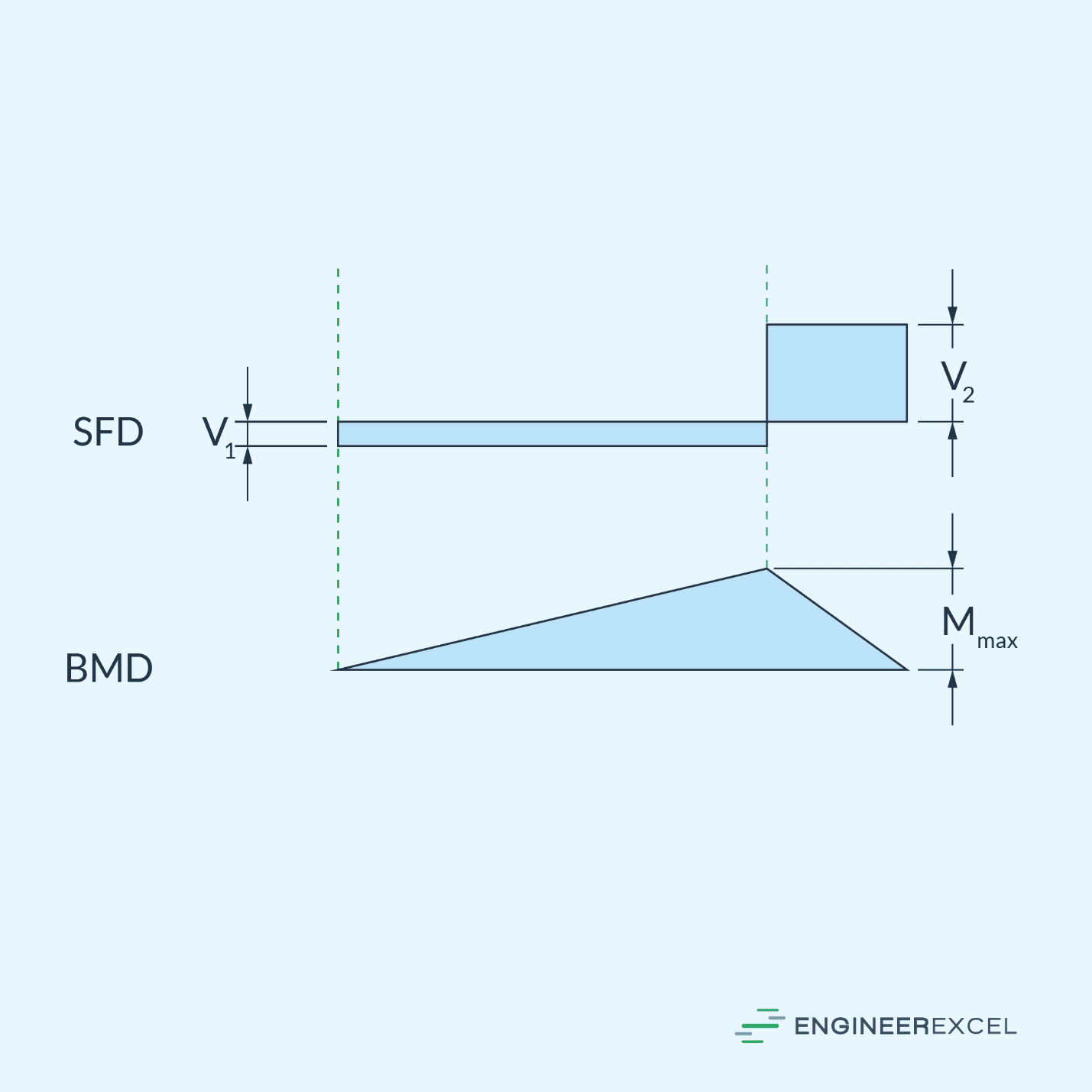
In the diagrams above:
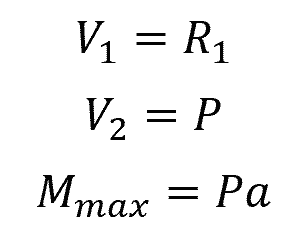
Where:
- V1, V2 = internal shear forces [N]
- Mmax = maximum bending moment at the roller support [N-m]