Shear diagrams are a graphical representation of the distribution of shear force along the length of a structural member, such as a beam. They are important for understanding internal stress distribution in a beam, allowing engineers to design structures accordingly and ensure the structural integrity and safety of the overall system.
Shear Diagrams Explained
When a beam is subjected to external loads, it experiences bending moments and shear forces. The shear force at a section of a beam is the force that acts perpendicular to the longitudinal axis, attempting to cause two segments to slide over one another.

Understanding this shear force is important for analyzing the internal stress distribution of a beam and its ability to withstand loading conditions. One way to illustrate the shear force behavior in a beam is through a shear diagram.
A shear diagram, also known as a shear force diagram, graphically represents the distribution of shear force along the length of a structural member, such as a beam. In this diagram, the horizontal axis represents the length of the structural element, while the vertical axis represents the magnitude and direction of the shear forces.

Elevate Your Engineering With Excel
Advance in Excel with engineering-focused training that equips you with the skills to streamline projects and accelerate your career.
The diagram typically starts at zero shear force and shows variations as one moves along the length of the structure. Key points on the shear diagram correspond to locations where external loads are applied, and abrupt changes or discontinuities in the diagram often indicate the presence of concentrated loads or support reactions.
Engineers use shear diagrams in conjunction with bending moment diagrams to analyze and design structures. By examining these diagrams, engineers can decide where to place reinforcement materials within the beam or how to proportion the size of the beam at various points along its length to ensure that no failure occurs.
Constructing Shear Diagrams
Support Reactions
To begin constructing shear diagrams, first determine the support reactions. These reactions are the forces exerted by supports to counteract the applied loads, ensuring the beam remains in equilibrium.
These reactions are calculated using the following equilibrium equations:
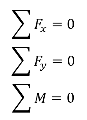
Where:
- Fx = horizontal forces [N]
- Fy = vertical forces [N]
- M = moments [N-m]
By solving these equations simultaneously, the unknown support reactions can be determined.
Shear Sign Convention
After determining all the applied loads and support reactions, the shear diagram can be created by expressing the shear force as a function of its position x along the beam’s axis. While the choice of origin is arbitrary, it is typically located at the left end of the beam, with the positive direction to the right.
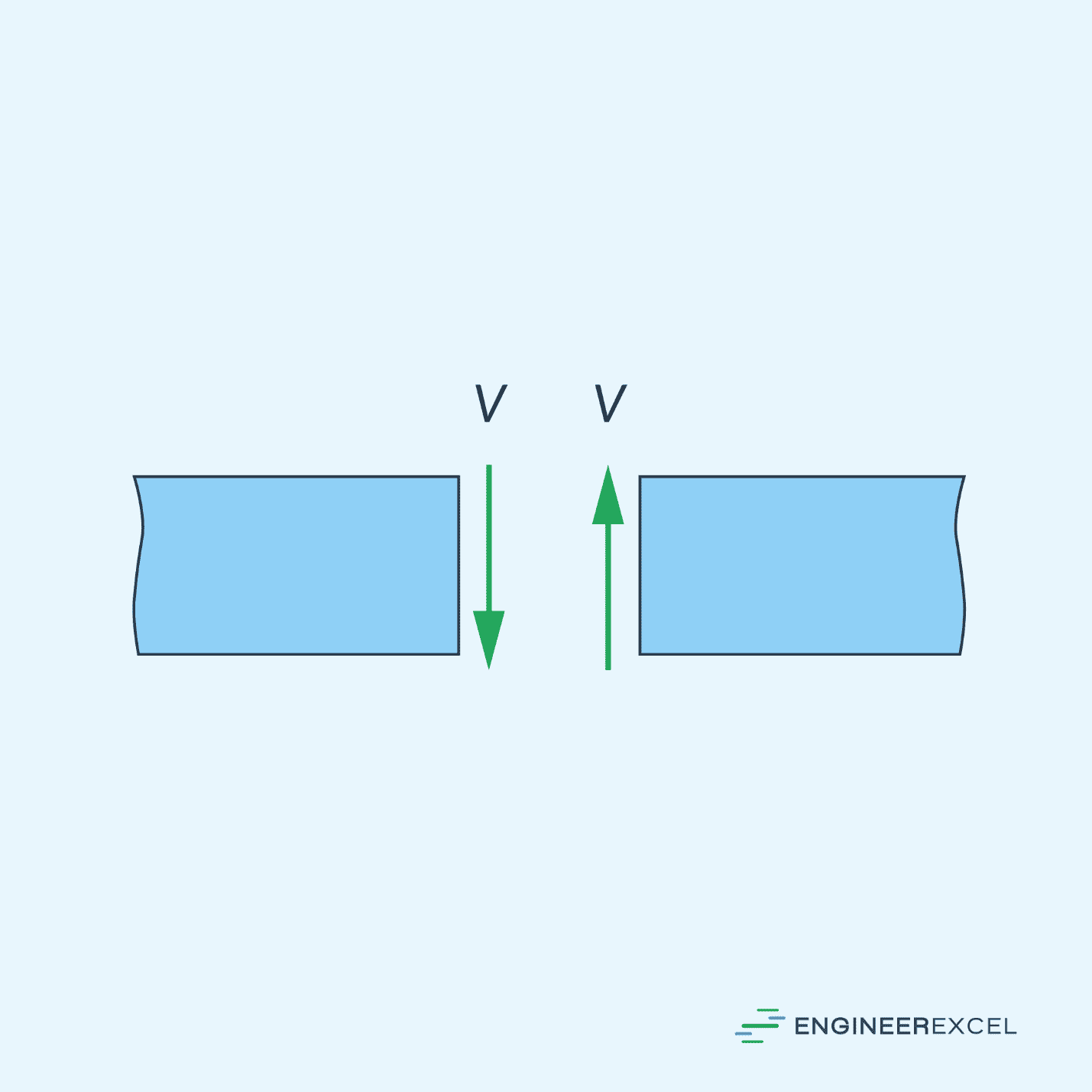
Generally, the sign convention for the internal shear force is positive if it causes a clockwise rotation of the beam segment on which it acts, as depicted in the diagram below; otherwise, it is negative.
Drawing the Shear Diagram
Calculate the shear forces at key points along the beam. These points include locations where concentrated loads, point loads, and distributed loads are applied.
In order to do this, section the beam at these points, and draw the free-body diagram of one of the segments. The shear is obtained by summing forces perpendicular to the beam’s axis
Once the shear forces are known at all key points, begin drawing the shear diagram at one end of the beam. If there are support reactions, draw them as step changes at the supports.
Move along the beam and indicate any changes in shear force due to applied loads. For point loads, draw a vertical step change equal to the magnitude of the load. For distributed loads, draw a sloping line or curve whose slope is equal to the load intensity.
Continue drawing the shear diagram until you reach the other end of the beam. If there are support reactions at the other end, represent them as step changes.
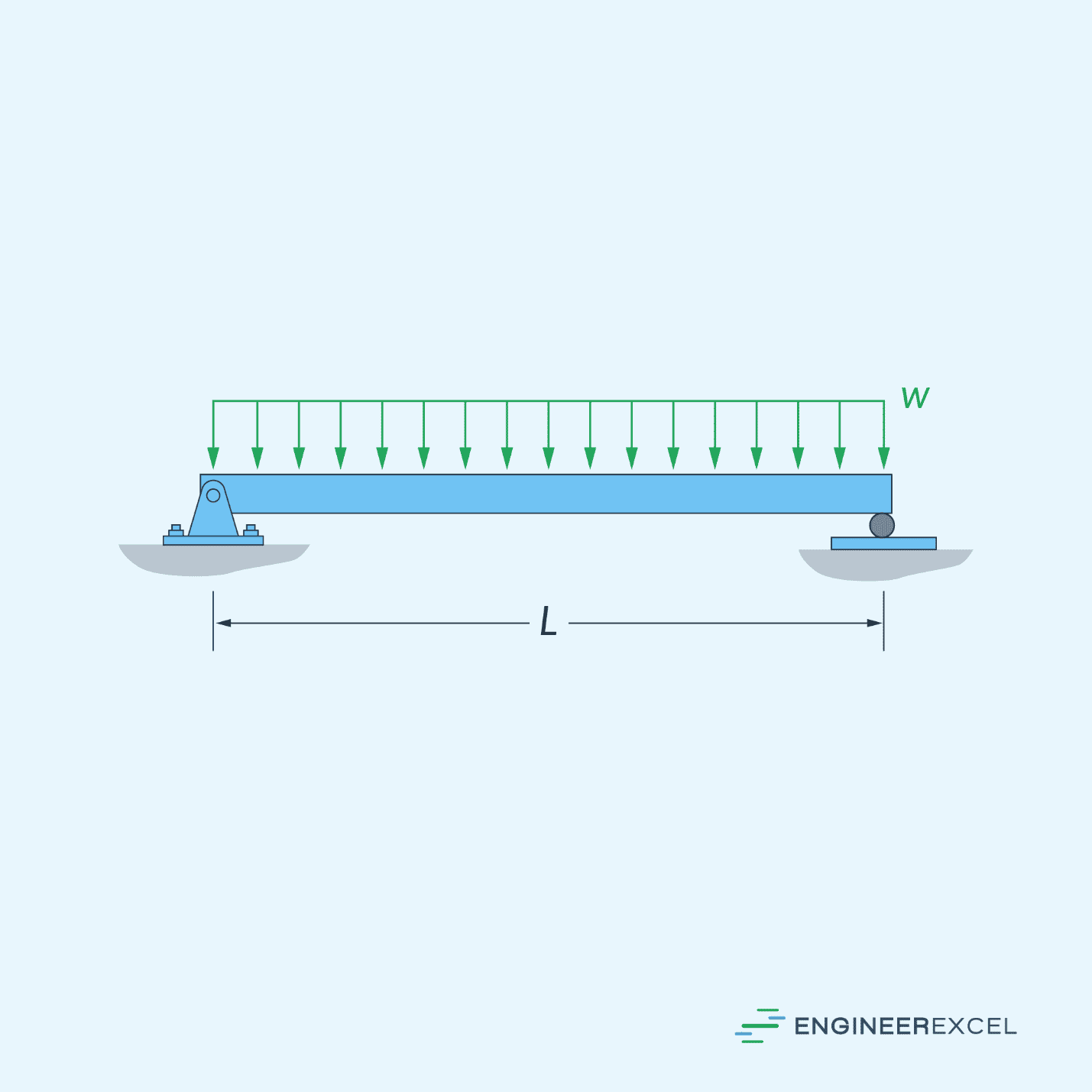
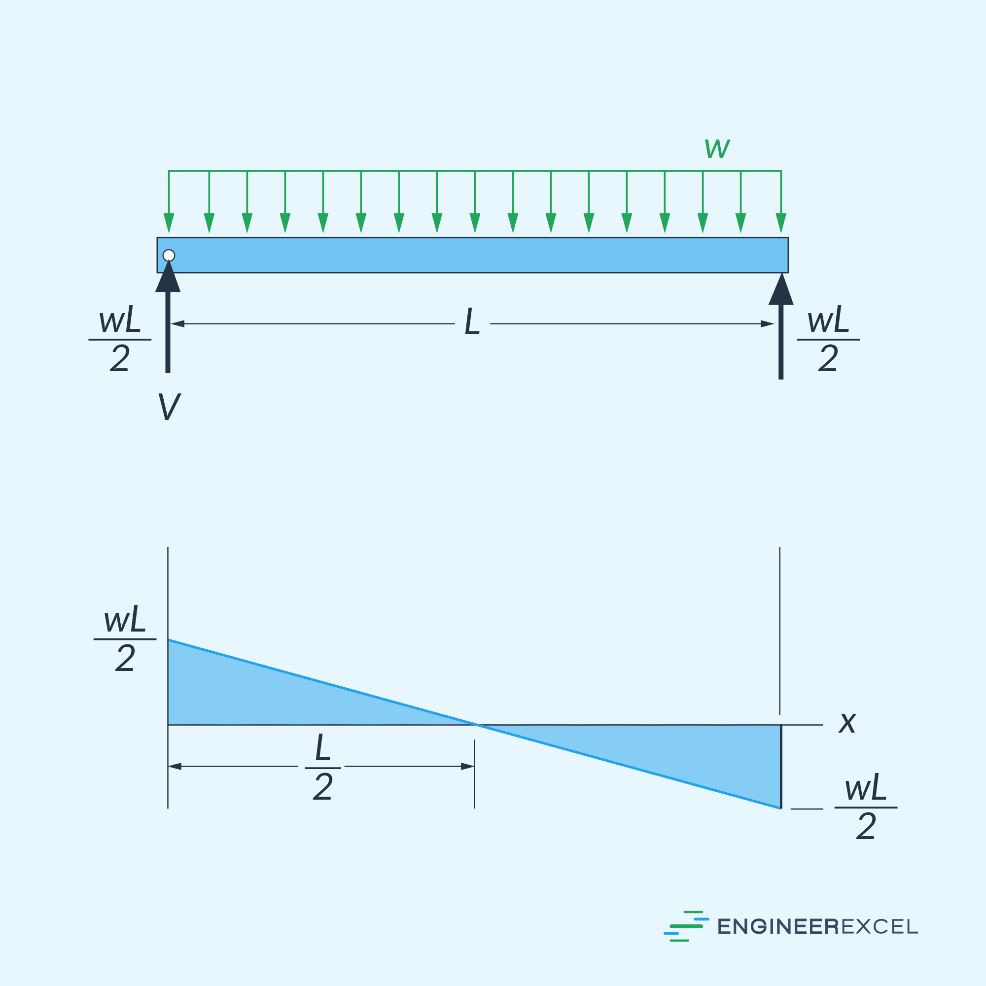
Shear Diagram for Uniform Load
As an example, the diagram below shows the shear diagram of a simply supported beam of length L subjected to a uniform loading.
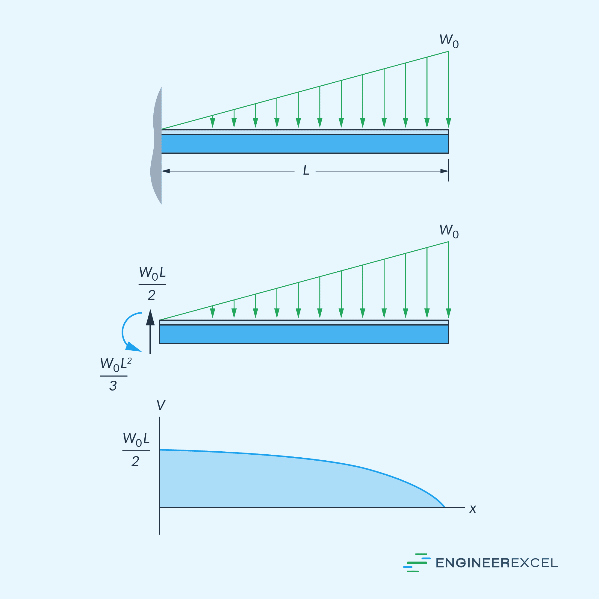
Shear Diagram for Triangular Distributed Load
In another example, the diagram below shows the shear diagram of a cantilever beam of length L subjected to a triangular loading.