A continuous beam is a horizontal structural element that spans over multiple supports, in contrast to simple beams that have at most two supports. This design offers enhanced structural stability and load distribution, making it particularly advantageous for long-span applications such as roofs, floors, or bridge deck systems.

In this article, we will discuss the characteristics, applications, and analysis of continuous beams.
What is a Continuous Beam
Beams are essential structural elements of buildings and bridges, designed to support the loads imposed on them. A beam is a horizontal member that is supported at its ends and subjected to transverse loads, such as those produced by a roof, floor, or bridge deck system. Based on their support conditions, beams are categorized into different types, such as simple beams, cantilever beams, and continuous beams.
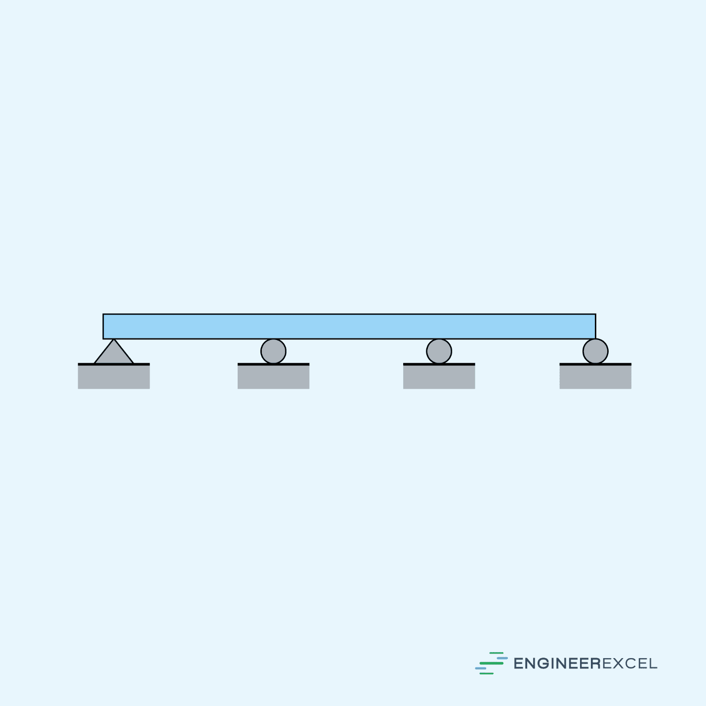
A continuous beam is a type of structural beam that extends over multiple supports. This design provides increased structural stability and load distribution, compared to a simple beam with only two supports.

Elevate Your Engineering With Excel
Advance in Excel with engineering-focused training that equips you with the skills to streamline projects and accelerate your career.
In a continuous beam, the load is distributed across the entire length of the beam, resulting in a more uniform stress distribution. The spans between the supports are called continuous spans. The number of continuous spans in a beam affects its stress distribution and deflection behavior.
In general, continuous beams are considered statically indeterminate structures, which means that their reactions and internal forces cannot be determined using only the equations of equilibrium. This is because of the redundant supports in between the spans, which introduce additional unknown support reactions. Hence, the analysis of such structures requires additional equations, which can be formulated using conditions of geometry.
Applications of Continuous Beams
Continuous beams are widely used in various engineering applications to efficiently support loads. Some common applications include bridge structures, building frameworks, and conveyor systems.

In bridge structures, continuous beams help in evenly distributing the loads applied on the bridge along with its entire span, such as vehicular and pedestrian traffic or wind loads.
For building frameworks, continuous beams are typically used in the construction of high-rise buildings, industrial facilities, and aircraft hangars. There, they contribute to both structural strength and stability by supporting the loads applied to the framework, such as the weight of the structure and various live loads.
In conveyor systems, continuous beams are used in the design of overhead material handling systems, such as cranes and monorails. They support the conveyor track and withstand loads from the moving equipment and the materials being transported. These beams must be designed to handle the specific static and dynamic loadings of these systems, which may include forces induced by start-stop motions, material weights, and lateral forces due to acceleration.
Continuous Beam Analysis
Deflection of a Continuous Beam
A typical deflection curve of a continuous beam subjected to uniform loading is shown in the diagram below.
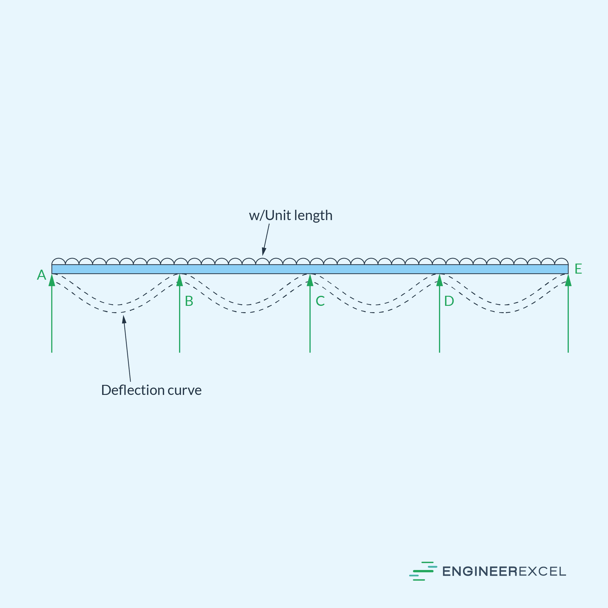
Assuming that the load is directed downwards, the deflection curve for a continuous beam is concave downwards over the intermediate supports and concave upwards over the mid-span. Consequently, the bending moment is negative over the intermediate supports and positive over the mid-span.
Bending Moment of a Continuous Beam
In order to draw the bending moment diagram of a continuous beam, the first step is to determine the moments at the intermediate supports. One way to do this is through Clapeyron’s Theory of Three Moments.
The traditional static equilibrium equations (sum of forces and sum of moments equal to zero) are not sufficient to solve indeterminate structures, where the number of unknowns exceeds the available equations. Clapeyron’s Theory of Three Moments addresses this limitation by introducing additional equations based on the continuity of bending moments along a structure. This theory is an extension of the traditional static equilibrium equations and provides a more comprehensive approach to analyze indeterminate structures, like continuous beams.
To illustrate this theory, consider the diagram of the continuous beam above. According to this theory, the moments at the supports for two consecutive spans (BC and CD) under external loading can be determined using the following equation:
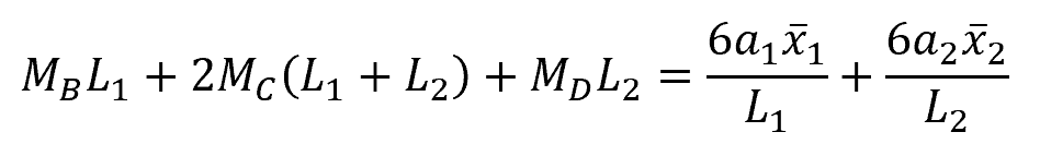
Where:
- MB, MC, MD = moments at the intermediate supports [N-m]
- L1 = length of span BC [m]
- L2 = length of span CD [m]
- a1 = area of bending moment diagram due to vertical loads on span BC [N-m2]
- a2 = area of bending moment diagram due to vertical loads on span CD [N-m2]
- x̄1 = distance of the center of gravity of the bending moment diagram due to vertical loads on span BC from point B [m]
- x̄2 = distance of the center of gravity of the bending moment diagram due to vertical loads on span CD from point D [m]
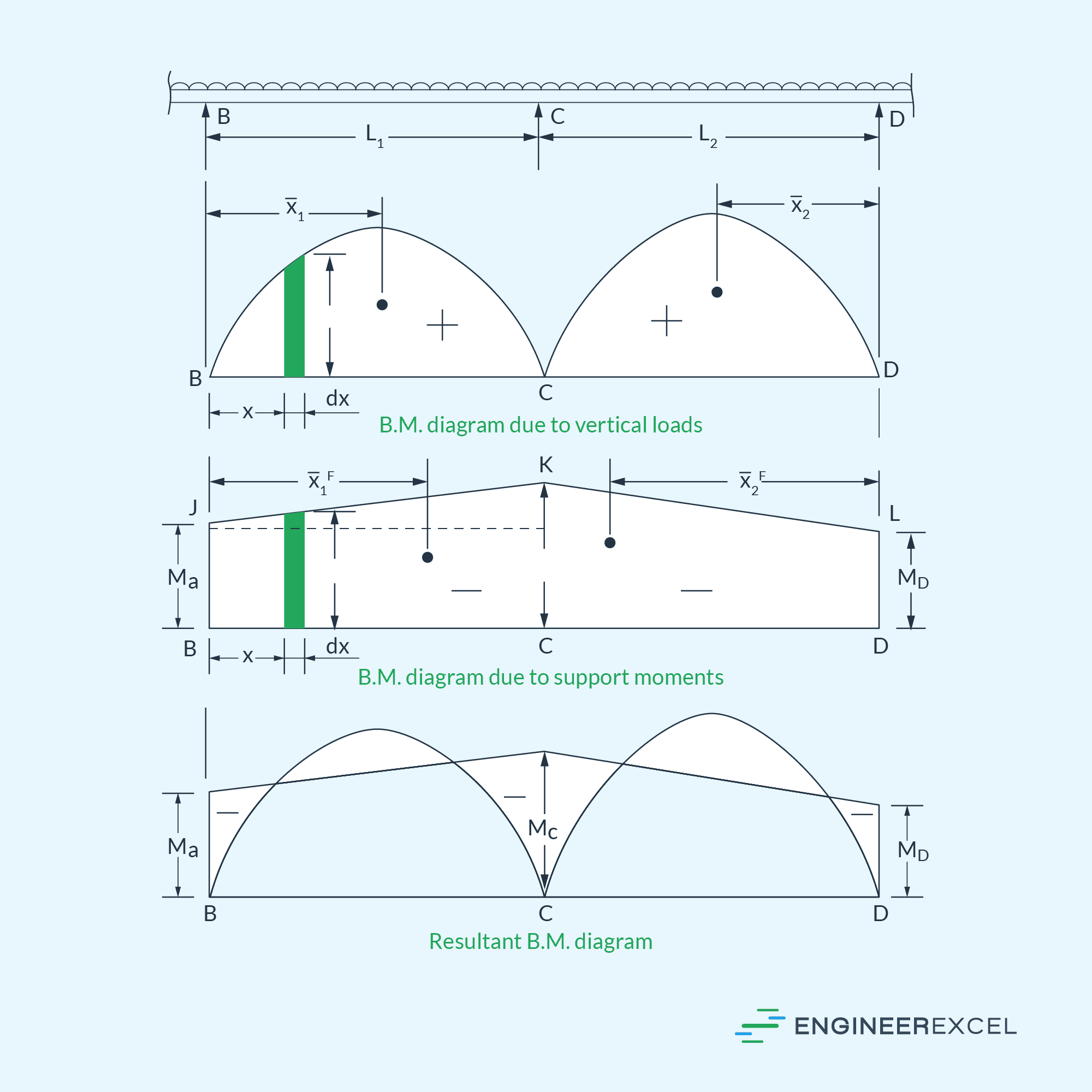
This equation is referred to as the equation of three moments. By utilizing this equation, the moments at the supports can be calculated. The resultant bending moment diagram can then be obtained by combining the bending moment diagram due to vertical loads with the bending moment diagram due to the support moments, as depicted in the diagram below.