In beam design, a distributed load refers to a force or load that is spread out along the length of a beam rather than being concentrated at a single point. It is typically expressed per unit length and can exert varying amounts of force at different points along the beam.
In this article, we will discuss the different types of distributed load and their method of analysis.
What is a Distributed Load
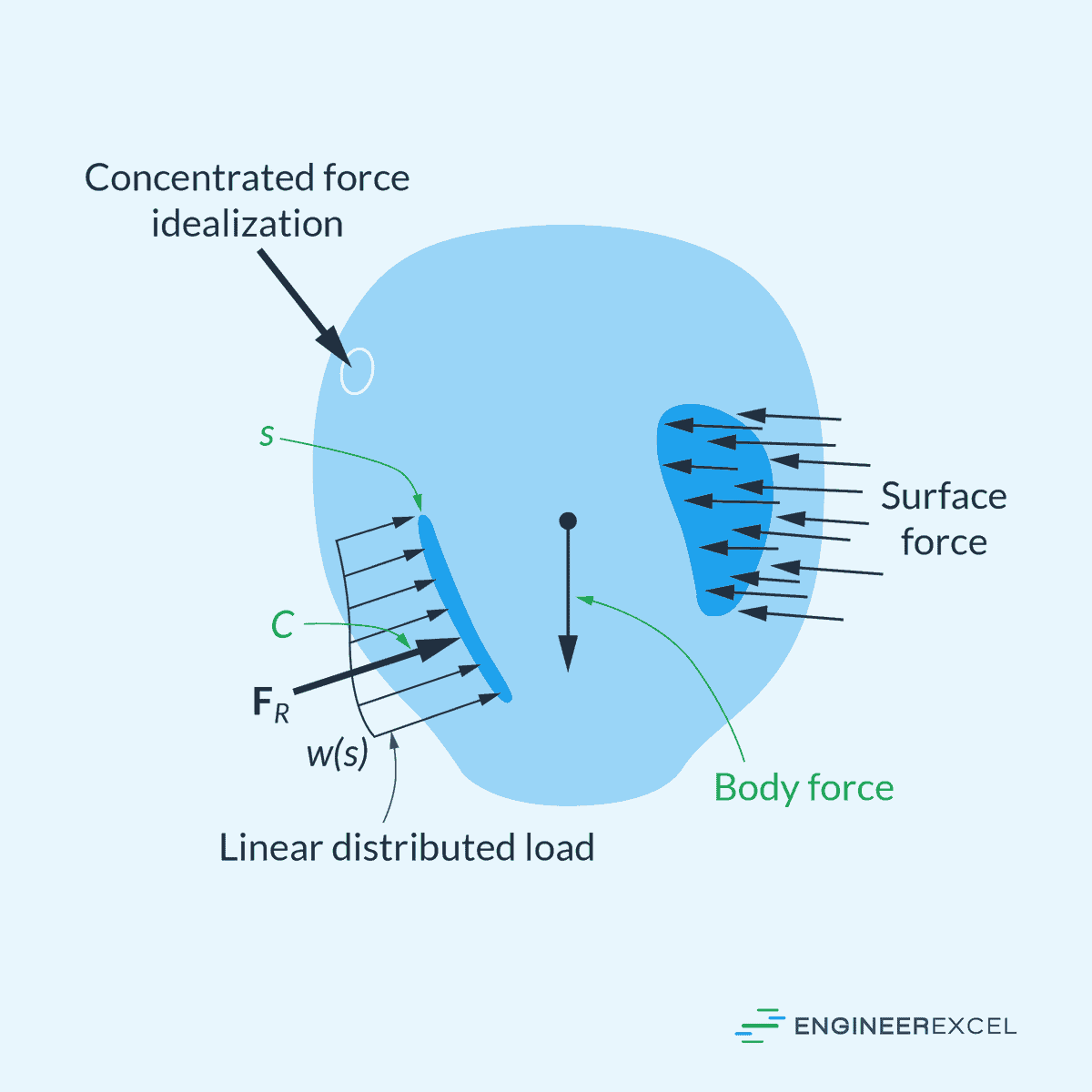
Surface force occurs when one body makes direct contact with another surface. If the contact area is much smaller than the total surface area, the force can be simplified as a single concentrated force applied to a specific point, like a bicycle’s wheels on the ground.

Elevate Your Engineering With Excel
Advance in Excel with engineering-focused training that equips you with the skills to streamline projects and accelerate your career.
However, if the contact area is significant, the force is typically analyzed as a distributed load, which means that the force is spread out over an area. For narrow contact areas, it is more appropriate to think of it as a linear distributed load. This is commonly seen in beams where the load is distributed over its length.
A linear distributed load is applied continuously along a certain length rather than at a single point. This can include loads such as weight of materials, self-weight of components, wind or hydrodynamic pressures, and other forces. Its intensity can vary from one point to another and is typically measured in force per unit length, such as Newtons per meter (N/m) or pounds per foot (lbs/ft).
Types of Distributed Load
Uniformly Distributed Load
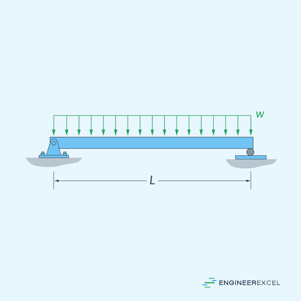
A uniformly distributed load (UDL) is a type of distributed load where the intensity of the force remains constant across its entire length. This means that the force per unit length acting on the structure is the same at every point, as shown in the diagram below. For example, a horizontal beam supporting a uniform load such as a ceiling or floor.
Varying Distributed Load
Under a varying distributed load, the intensity of the force changes along the length of the distribution. This type of load can be further classified into two subcategories: linearly varying and nonlinearly varying.
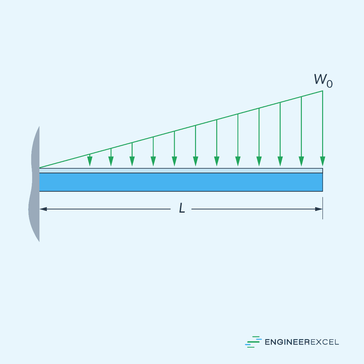
A linearly varying distributed load, also known as a triangular load, increases or decreases linearly along the length or area of application, as shown in the diagram below. This can occur when a structure supports an inclined plane, such as a sloping roof subjected to snow load.
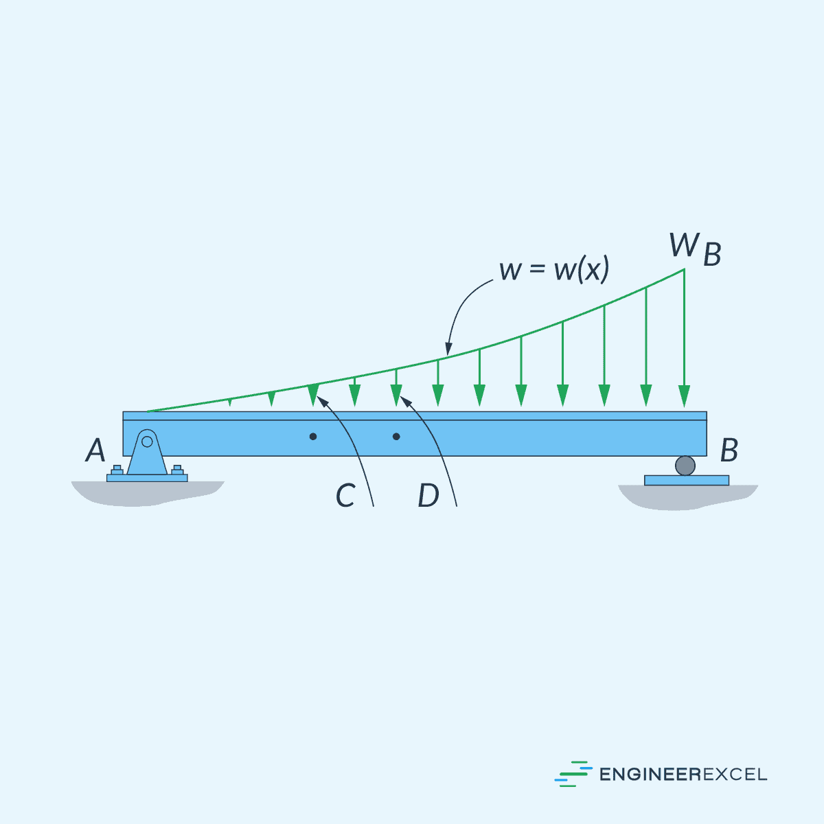
On the other hand, a nonlinearly varying distributed load refers to any load whose intensity distribution does not follow a linear relationship, such as the example shown below.
Combined Distributed Load
In real-world engineering applications, structures may be subjected to a combination of distributed load types. A combined distributed load is the superposition of multiple distributed loads acting on the structure simultaneously. For example, a bridge might be subjected to both uniformly distributed load from its own weight and varying distributed load from traffic.
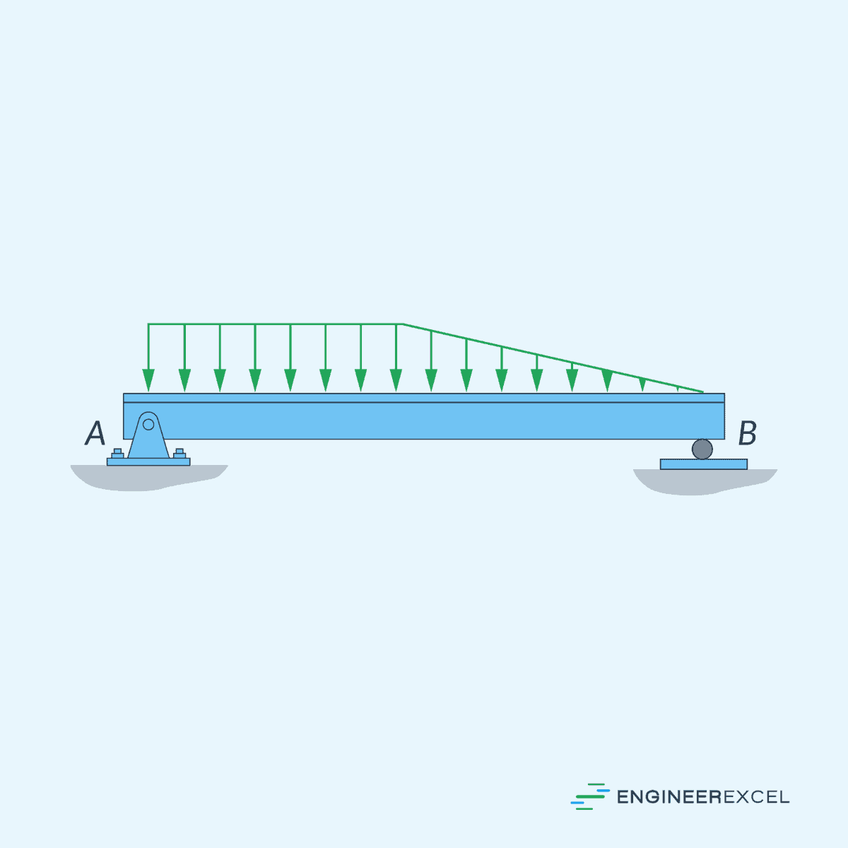
When calculating the total resultant force and its point of application for combined distributed loads, each distributed load should be analyzed separately, and the results should be summed to obtain the overall resultant force and its location.
Analysis of Distributed Loads
There are various methods for analyzing distributed loads. One common approach involves using equivalent systems, where a distributed load is simplified into a single resultant force acting on the centroid of the loading curve.
The total or resultant force of a distributed load can be found by integrating the load distribution along the given length. This is analogous to the magnitude of a concentrated load that would have the same effect on the structure if applied.
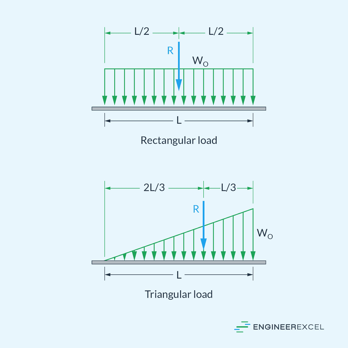
For instance, if a beam has a uniform loading (wo) across its length, you can calculate the resultant force by multiplying the uniform load (wo) by the length (L) of the beam. The resultant force (woL) applies at the centroid of the rectangular load diagram, which, in this case, is positioned at the center of the beam.
On the other hand, for a triangular distributed loading with a maximum magnitude of wo, the resultant force is equal to the area under the triangular diagram, woL/2. This resultant force is applied at the centroid of the triangular load diagram, which, in this case, is positioned at a distance L/3 from the location of the maximum load magnitude.
These are illustrated in the diagrams below.