
The maximum shear strain represents the peak magnitude of shear deformation in an element, measured as the change in angle between initially perpendicular segments within the element. It happens when the element is oriented in a way that maximizes the shear strain component and equalizes the normal strain component to the average normal strain.
This article explores the calculation of maximum in-plane shear strain, the orientation of the plane at which it occurs, and the utilization of Mohr’s Circle for determining the maximum shear strain.
Understanding the Maximum Shear Strain
The deformation of a material can be categorized into two types: shear strain and normal strain. Shear strain represents the change in shape due to shearing forces, while normal strain represents the change in length of a material.
In general, the deformation of a three-dimensional material can be represented by three components of shear strain (γ) and three components of normal strain (ε). However, in the case of plane strain, which considers only two dimensions of the material, this can be simplified to just two components of normal strain and one component of shear strain.

Elevate Your Engineering With Excel
Advance in Excel with engineering-focused training that equips you with the skills to streamline projects and accelerate your career.
The values of these strain components will depend on the orientation of the element. Therefore, by rotating the element, it can be oriented in such a way that the maximum shear strain occurs. At this orientation, there is an associated normal strain equal to the average normal strain.
Determining the maximum shear strain is important as it provides critical insights into the deformations and potential failure mechanisms of materials under stress. Identifying the orientation at which the maximum shear strain occurs can help engineers design structures with adequate resistance to shear failure under various loading conditions.
Calculation of Maximum Shear Strain
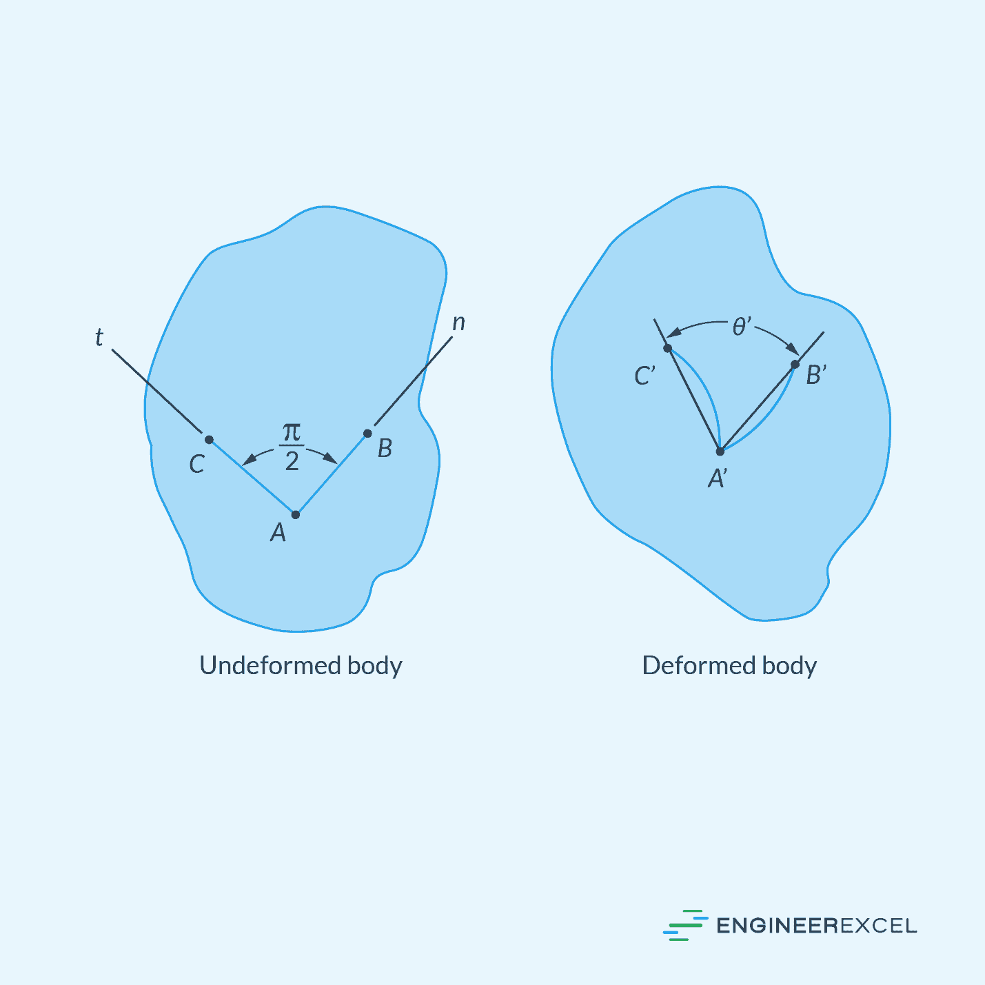
Shear strain refers to the deformation experienced by a material when subjected to a force that causes particles in the material to slide past one another. Specifically, it indicates the change in angle between two originally perpendicular segments in a material, as shown in the following diagram.
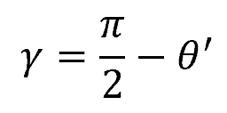
Mathematically, shear strain can be calculated using the following formula:
Where:
- γ = shear strain [rad]
- θ’ = angle between the segments after deformation [rad]
Now consider an element subjected to one component of shear strain (γxy) and two components of normal strain (εx and εy), shown in the diagram below.
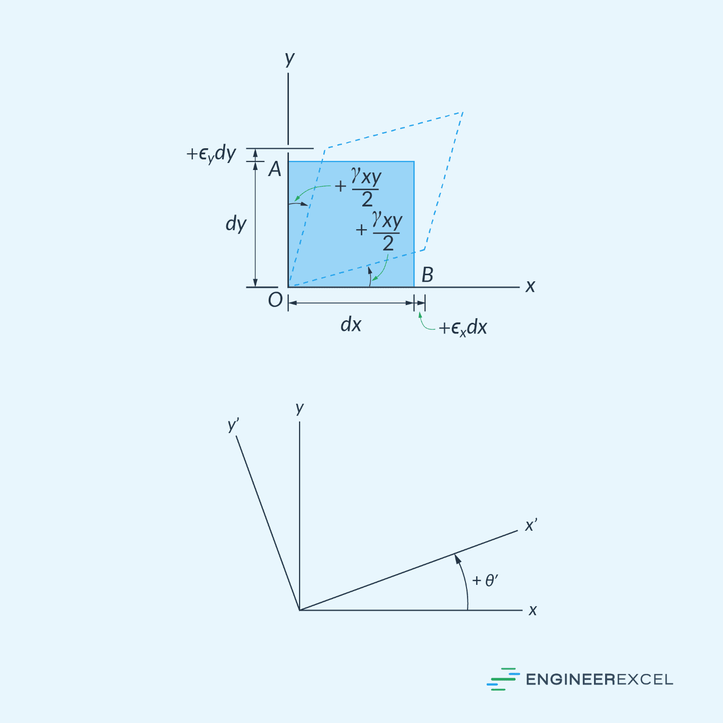
To determine the orientation of the x’-y’ plane at which the maximum shear strain would occur, the following formula can be used:
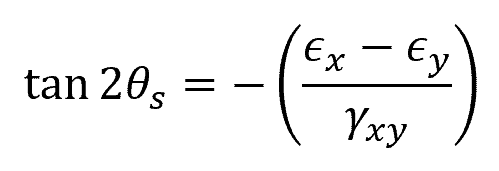
Where:
- θs = angle between the x and x’ axes [rad]
- γxy = original shear strain [rad]
- ϵx = original normal strain along x axis [unitless]
- ϵy = original normal strain along y axis [unitless]
Keep in mind that the sign convention for θs follows the right-hand rule. This means that θs is considered positive when the x’ axis is oriented counterclockwise from the x axis, and negative when it is oriented clockwise. The orientation for maximum shear strain is typically at 45 degrees from the plane of principal strains.
To obtain the magnitude of the maximum in-plane shear strain, the following formula can be used:
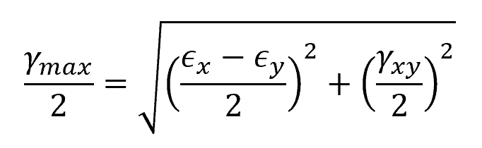
Where:
- γmax = maximum in-plane shear strain [rad]
As mentioned above, there is also an associated average normal strain that occurs on this orientation. This can be calculated using the formula:
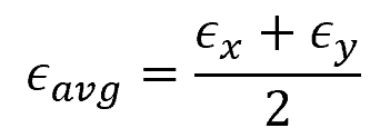
Where:
- ϵavg = average normal strain [unitless]
Determining Maximum Shear Strain Using Mohr’s Circle
Similar to stress, it is possible to use Mohr’s Circle to represent the states of strain of a material at different loading conditions. This is possible because the equations of plane-strain transformation are mathematically similar to the equations of plane-stress transformation.
In this case, the Mohr’s Circle for plane strain can be plotted with a center at C (ϵavg, 0) and a radius equal to half of the maximum in-plane shear strain (γmax/2). This is shown in the diagram below.
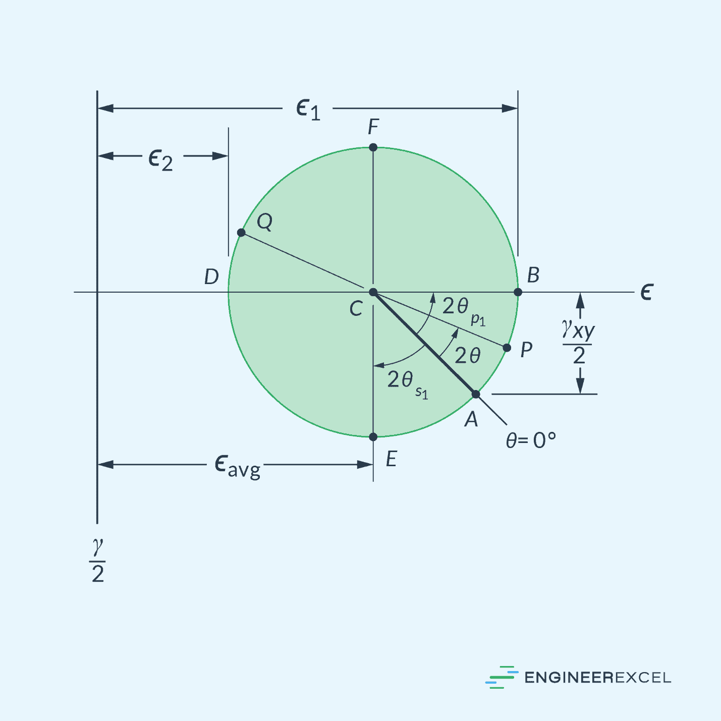
In the diagram above, the length from point E to point F represents the maximum in-plane shear strain.