
A fixed beam is a type of beam that is rigidly connected to its supports. This configuration prevents any movement or rotation at the connection points, resulting in greater structural rigidity compared to other beam types.
In this article, we will characterize fixed beams, including their practical applications and an analysis of bending moment diagrams, shear force diagrams, and points of contraflexure.
What is a Fixed Beam
Beams are a structural element that predominantly withstand loads by developing both shear and bending stress within the material. They are characterized by their method of support, cross-sectional shape, and material properties.
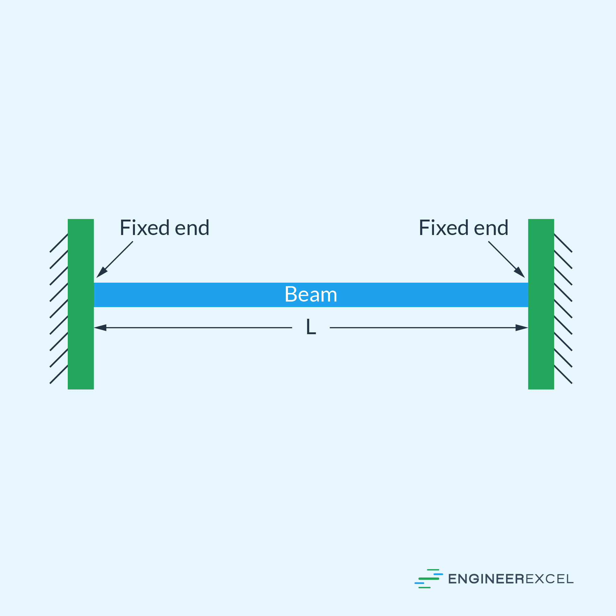
A fixed beam, also known as a built-end beam or restrained beam, is a type of beam that is rigidly connected to its supports, preventing any movement or rotation at the connection points. This is shown in the diagram below.

Elevate Your Engineering With Excel
Advance in Excel with engineering-focused training that equips you with the skills to streamline projects and accelerate your career.
Fixed beams are known for their greater rigidity compared to other beam types due to their fixed end conditions. This results in the development of additional constraint-based internal forces, which contribute to the overall moment resistance and load-carrying capacity of the beam. These constraint-based forces differ from those in simply supported or cantilever beams, which have either rotationally free or unsupported ends.
An important aspect of a fixed beam is the fact that it is generally classified as a statically indeterminate beam. This means that equilibrium equations alone are insufficient to determine all the support reactions and internal forces within it. In other words, the number of unknowns exceeds the number of available equilibrium equations, requiring additional compatibility or deformation equations to fully analyze the beam’s behavior.
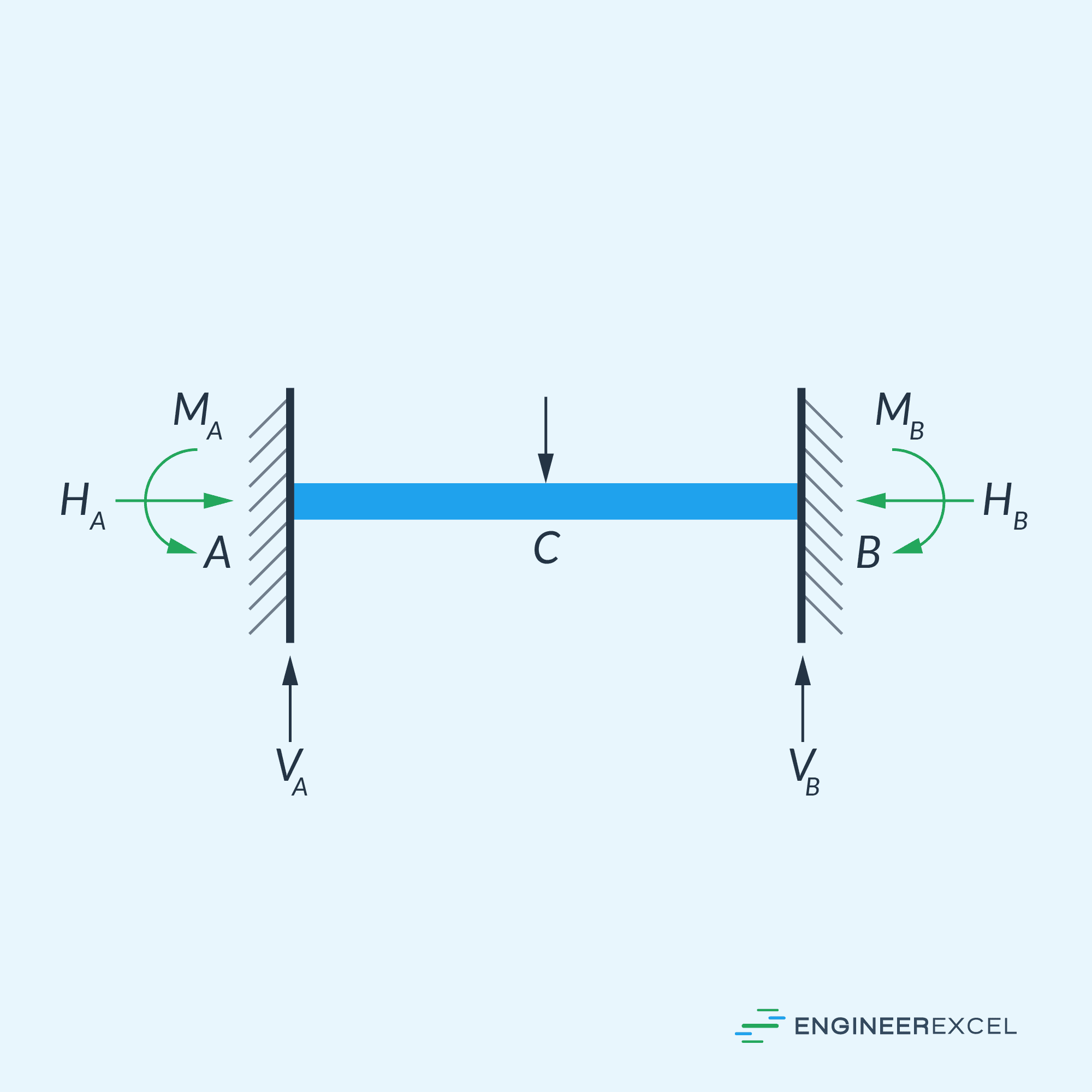
As shown in the diagram above, each fixed support comprises three reactions: a horizontal reactive force, a vertical reactive force, and a fixing end moment. When dealing with pure vertical loads, the horizontal reactive force reduces to zero.
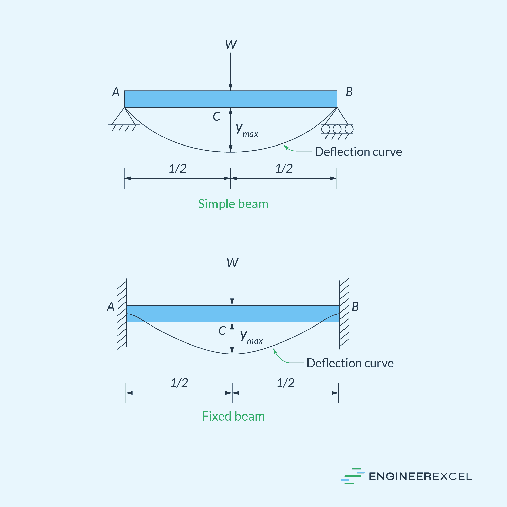
Due to the presence of a negative bending moment at the fixed ends that counteracts the positive bending moment caused by the load, the overall bending moment is decreased. As a result, both bending stress and deflection are reduced in comparison to an equivalent simple beam, as depicted in the diagram below. The slope and deflection at the fixed supports of the beam are zero.
It is important to ensure perfect alignment of the beam at the supports to prevent excessive stresses. Additionally, the fixed ends are susceptible to vibrations and fluctuations when subjected to cyclic loading.
Applications of Fixed Beams
One primary application of fixed beams is in building and bridge construction. They provide support for various structural elements, such as floor slabs, roof structures, and bridge decks. Fixed beams are rigidly connected to their supports, preventing rotation or translation at those points.
In the field of aerospace engineering, fixed beams are used to design and analyze wing structures and fuselage elements of aircraft. Due to their high bending stiffness, fixed beams are capable of transmitting forces and moments between different parts of an airframe, ensuring the structural integrity of the entire aircraft during flight.
Mechanical systems like cranes and hoists utilize fixed beams as well. The beams provide support and prevent excessive deflections, enabling the safe and smooth movement of loads. Furthermore, fixed beams are also used in machinery, particularly in components that require resistance against bending and torsional forces.
Fixed Beam Analysis
Bending Moment Diagram
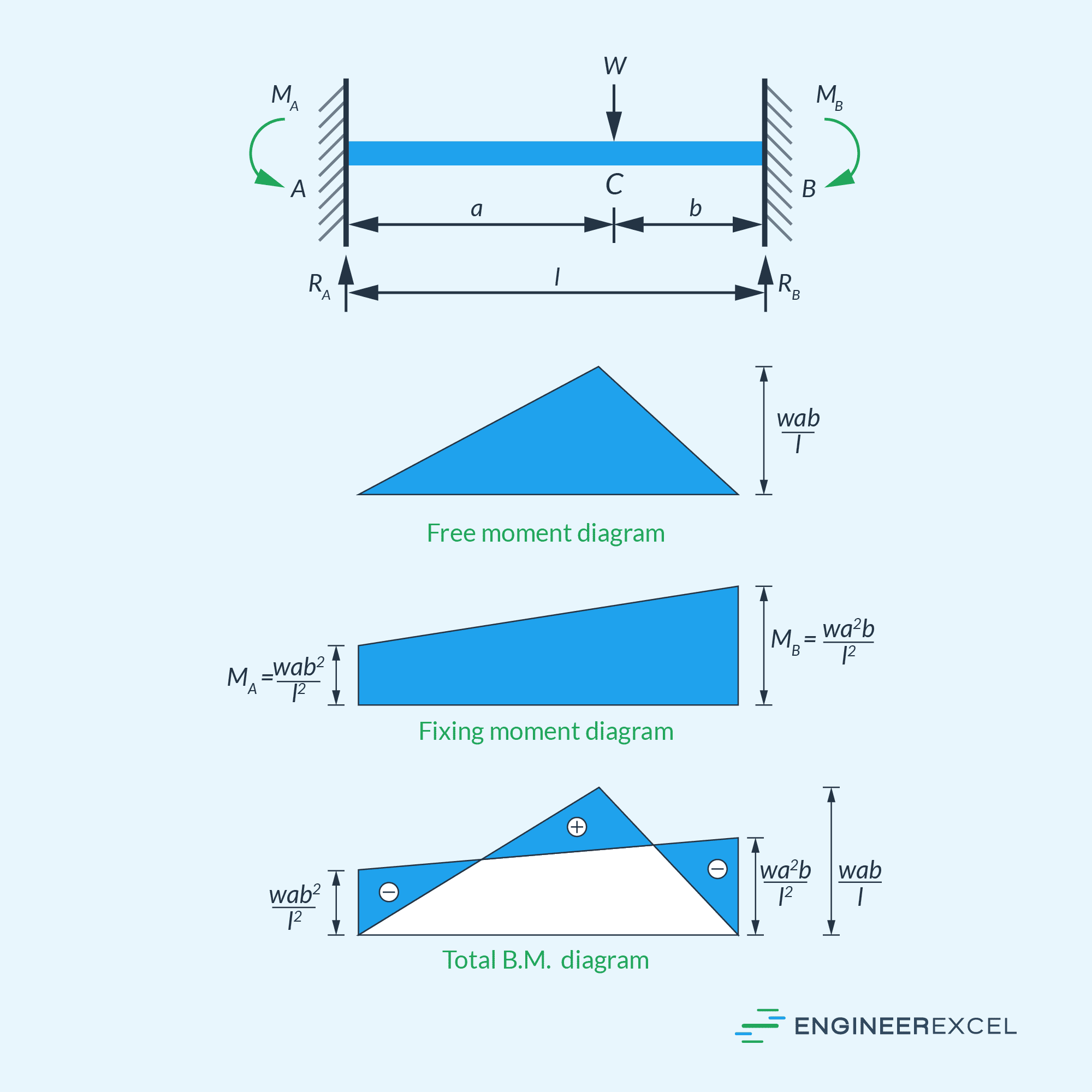
Compared to simply supported beams, which have zero bending moments at the end supports, fixed beams exhibit negative bending moments at the fixed end supports. This counteracts the positive moment caused by the load at the middle portion of the beam.
Therefore, the bending moment diagram of a fixed beam is a combination of two components: the first component is the positive bending moment considering only the load, known as the free moment diagram, and the second component is the negative bending moment considering only the fixing moments at the end supports.
The area of the free moment diagram is equal to the area of the fixing moment diagram. Additionally, the centroidal distance of both moment diagrams is equal from either support of the beam. By utilizing these conditions, the fixing end moment reactions at the supports can be determined.
To give an example, the moment diagrams of an eccentrically loaded fixed beam are illustrated below.
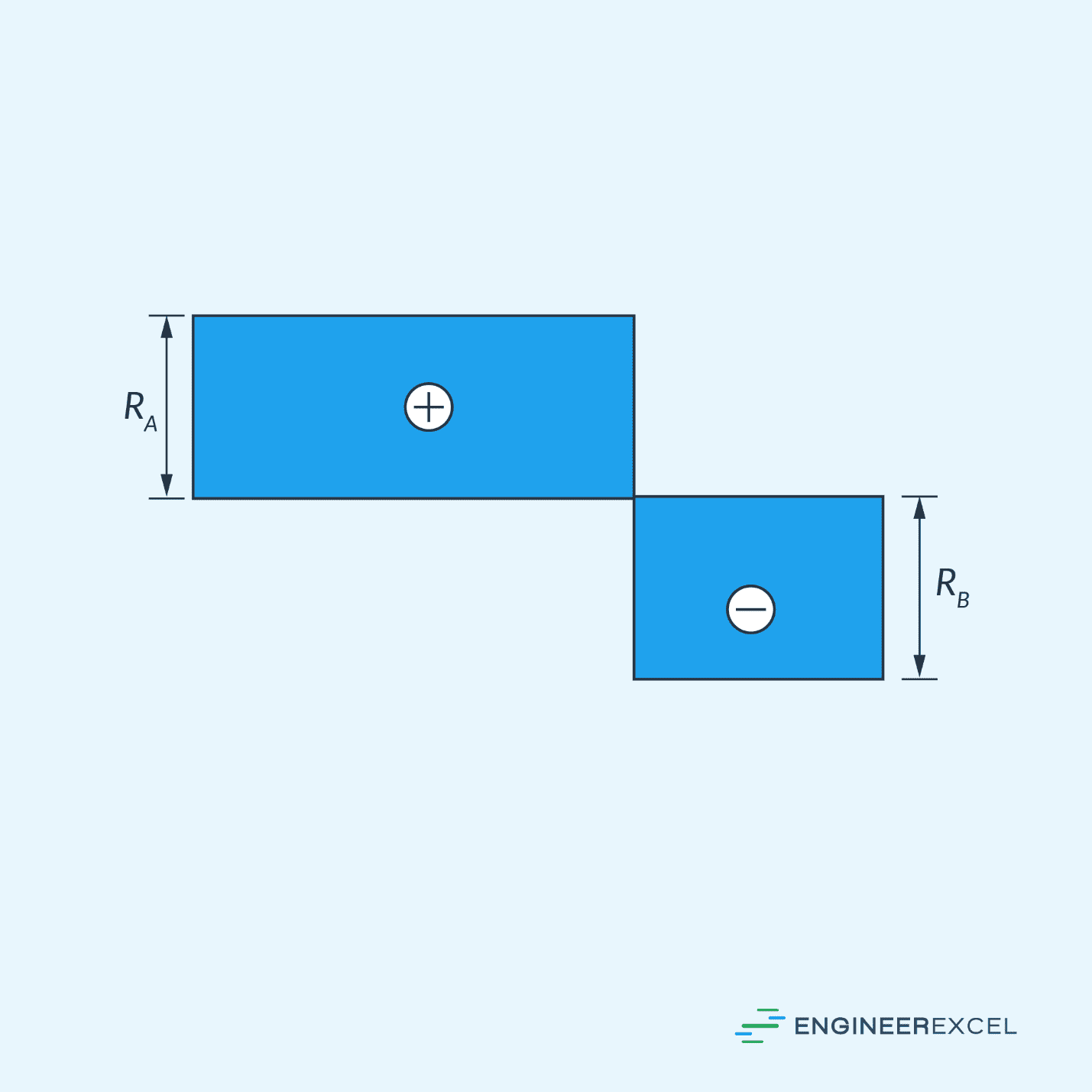
Shear Force Diagram
Once the values of the fixing moments are known, the reactive forces at the supports can be calculated using equilibrium equations. Then, the shear force diagram can be constructed as follows:
Point of Contraflexure
It is also important to understand the Point of Contraflexure, which refers to the location along a beam where the bending moment changes its sign, transitioning from a positive to a negative value or vice versa. At this point, the bending moment is zero.
For a fixed beam with no intermediate supports, there are two points of contraflexure near each end. By identifying the points of contraflexure, engineers can concentrate on reinforcing or modifying the beam to prevent any structural failures at these critical locations.