
Transverse shear stress refers to the internal resistance within a material that acts parallel to a plane or surface. In beams, it occurs when there are transverse loads applied perpendicular to the longitudinal axis of the beam.
In this article, we will discuss the concept of transverse shear stress and its calculation.
What is Transverse Shear Stress
Shear stress is the internal resistance within a material that acts parallel to a plane or surface. In beams, shear stress occurs when there is a force or load applied parallel to the cross-sectional area of the beam, causing the material to deform or slide along that plane. It typically arises due to transverse loads, such as forces or moments applied perpendicular to the longitudinal axis of the beam.
Mathematically, shear stress is defined as the intensity of the shear force distributed over the cross-sectional area of the material, as shown in the following equation:

Elevate Your Engineering With Excel
Advance in Excel with engineering-focused training that equips you with the skills to streamline projects and accelerate your career.
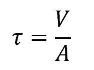
Where:
- τ = shear stress [Pa]
- V = internal shear force [N]
- A = cross-sectional area [m2]
Due to its complementary property, shear stress has two components: a transverse shear stress, which acts along the same plane as the transverse load, and a corresponding longitudinal shear stress, which acts along the longitudinal planes of the material. These shear stress components are complementary and numerically equal.
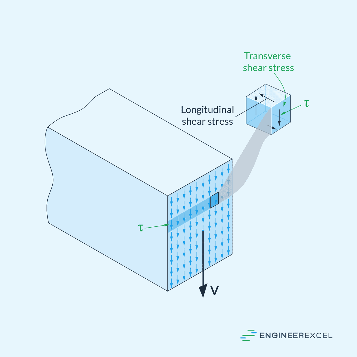
The magnitude of transverse shear stress is not uniform across the cross-section. In general, it varies from zero at the extreme top and bottom fibers to a maximum value at the neutral axis. In engineering applications, it is important to consider this phenomenon in order to design safe and efficient structures.
Calculating Transverse Shear Stress
When analyzing the performance of a beam against shearing forces, the first step is to determine the maximum internal resultant shear force along the length using equilibrium equations and shear-force diagram. Once the maximum internal shear force is known, the transverse shear stress at this point can be calculated using the shear formula:
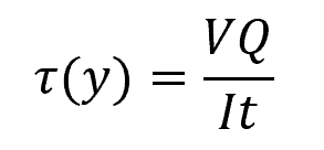
Where:
- τ(y) = shear stress at distance y from the neutral axis [Pa]
- V = internal shear force [N]
- Q = first moment of area between the segment of interest and the neutral axis [m3]
- I = moment of inertia of the entire cross-section [m4]
- t = width of the segment of interest [m]
This formula shows that shear stress at a point is dependent on the first moment of area of the segment, which in turn depends on the distance from the neutral axis, as shown in the equation below:
Where:
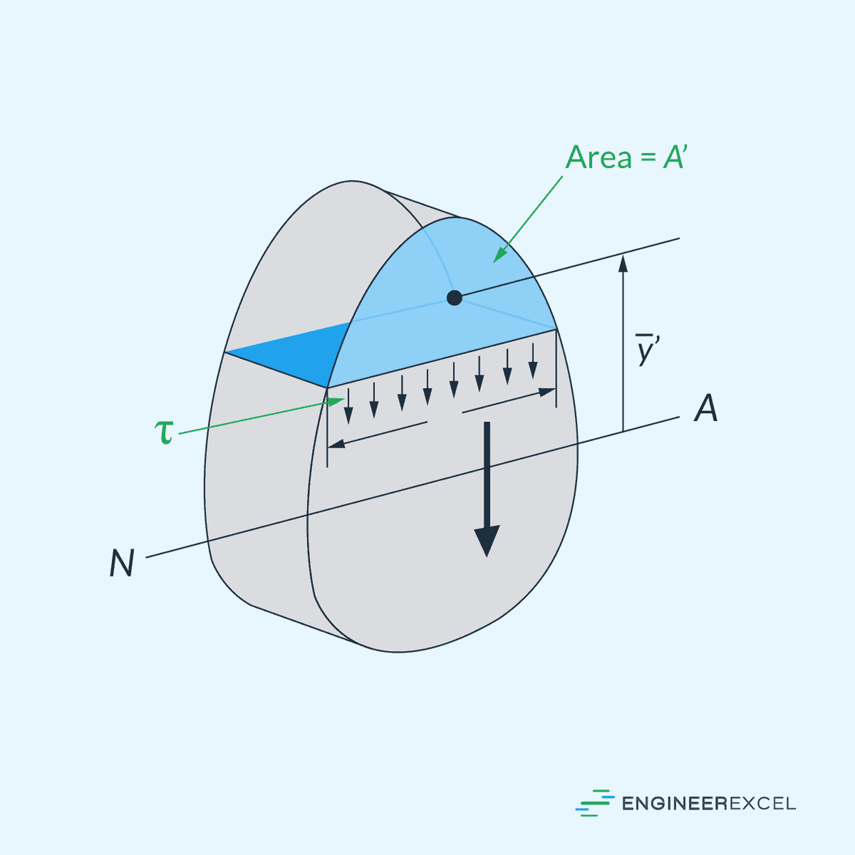
- A’ = area of the top (or bottom) portion of the member’s cross-sectional area, above (or below) the segment where t is measured [m2]
- ȳ’ = distance from the neutral axis to the centroid of A’ [m]
It is also important to note that the shear formula assumes an even distribution of shear stress across the entire width of the segment. While this may not precisely hold in reality, the variation is not substantial, making this assumption sufficient to simplify the analysis.
Example Problem
Problem: A rectangular beam with a thickness t=100 mm and a height h=200 mm is subjected to an internal shear force of V=10 kN. Calculate the transverse shear stress experienced by the beam at the neutral axis.
Solution:
The transverse shear stress at the neutral axis can be calculated by evaluating the shear formula at y=0:
We already know that V=10 kN and t=0.1 m. Let’s first calculate Q using the following formula:
A’ is the area of the portion above the segment of interest. Since our segment of interest is the neutral axis, this is simply equal to half of the total cross-sectional area:
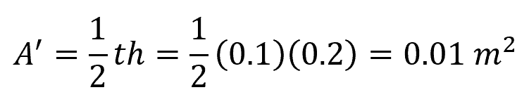
The variable ȳ’ is the distance from the neutral axis to the centroid of A’. In this case, it is equal to one-fourth of the total height, ȳ’=0.05 m. Therefore,

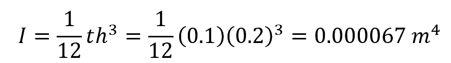
Next, calculate the moment of inertia. For a rectangular section, it is given by the formula:
Now, we can calculate for the transverse shear stress at the neutral axis:
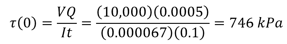
Therefore, the transverse shear stress at the neutral axis is 746 kPa.