The yielding moment of a structural member is an important parameter that is used when determining the maximum loads that can be applied to that member. It describes the moment that will lead to material yielding of the member, which will be a moment large enough to induce plastic deformation of the member. It is necessary to understand and utilize the yielding moment in structural design to ensure that a material with a large enough yield strength is used or that the moment-inducing loads will not cause the material to yield.

Derivation Of The Yielding Moment
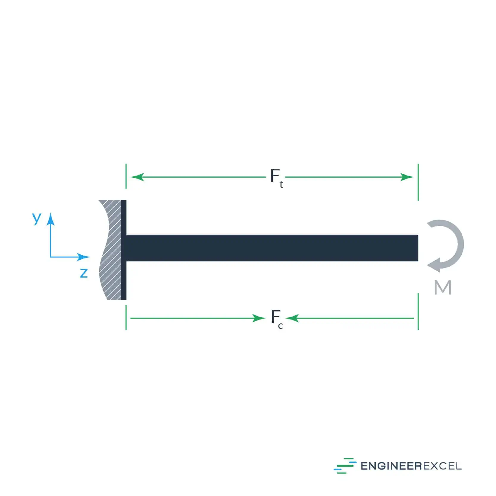
When a beam is subject to a moment M, it will cause a compression force Fc on one side and a tension force Ft on the other, as shown in the following figure:

For equilibrium to be satisfied,

Elevate Your Engineering With Excel
Advance in Excel with engineering-focused training that equips you with the skills to streamline projects and accelerate your career.

A force acting on a surface, A can be equated to the stress σ applied to that area,

Therefore,

where:
- σy is the yield stress, with SI units of N/m2 or Pa
- A1 is the area of the top section, with SI units of m2
- A2 is the area of the bottom section, with SI units of m2
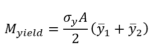
When the beam yields, the neutral axis of the beam will divide the cross-section into two equal areas, therefore,

where:
- Myield is the yielding moment, with SI units of N∙m
- Ft is the tensile force, with SI units of N
- Fc is the compressive force, with SI units of N
- is the distance from the top surface to the neutral axis, with SI units of m
- is the distance from the bottom surface to the neutral axis, with SI units of m
Because the top and bottom areas are the same,

Therefore,

The right side of this equation may look familiar as including the section modulus,

where S is the section modulus, with SI units of m3.
Finally, the yielding moment can be expressed as:

The above equation is a function of the cross-sectional shape of a structural member, which defines the value of S. So, although this derivation has focused on a rectangular cross-section beam, the same equation for the yielding moment can be used for any other cross section for which the section modulus can be determined and the yield stress is known.

Yielding Moment Example Calculation
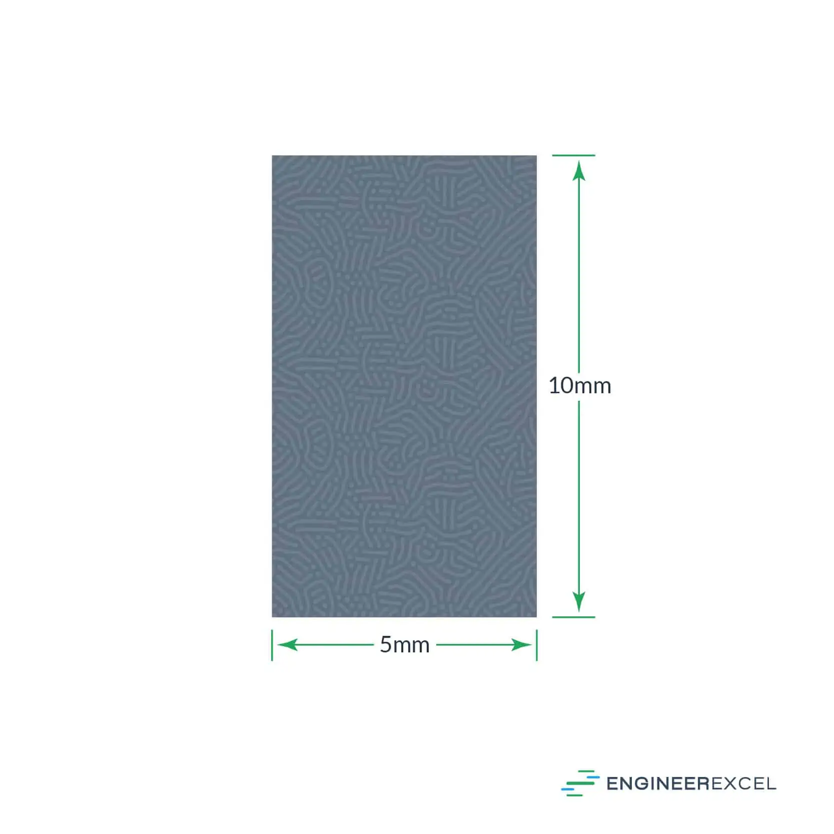
The following beam cross-section is used for an example calculation of the yielding moment:

The beam is fixed on one end and subject to a moment at the free end, as shown in the first drawing, above. The material of the beam is Al 6061 aluminum alloy, with a yield stress of 240 MPa. To find the maximum moment that the beam can withstand before yielding and deforming, the yielding moment equation is applied as follows.
- First, the section modulus S needs to be calculated for the rectangular beam. In this case, the general equation for the section modulus of a rectangular beam is used:

where:
- b is the base, or width, of the beam, with SI units of m
- h is the height of the beam, with SI units of m
Therefore,

- Second, the yielding moment equation can be applied to determine the moment that will lead to yield:

The Al 6061 beam with the cross section shown can withstand up to a moment without yielding and becoming plasticly deformed. The overall length of the beam will determine the actual force that can be applied, using the moment calculation equation to ensure the moment is less than Myield.
Application Of The Yielding Moment

As stated earlier, the yielding moment is a necessary value to calculate when considering materials to be used for structural engineering or the loads that will be applied to a structure. For example, the design of a bridge may consider the material used to determine the maximum loads that can pass across the bridge to alert users, such as vehicles, and ensure that the loads will not induce yielding and plastic deformation to the bridge.
