The shear center is the point on a cross-sectional plane where no twisting or rotation occurs in a beam when a load is applied. In this article, we will explain the concept of the shear center and its importance in beam design.
It covers how to find the shear center in symmetric sections, angular sections, and thin-walled open sections, as well as the formulas for determining the shear center location in commonly used thin-walled beam geometries.
What is the Shear Center?
The shear center, also called flexural center, refers to the point on a cross-sectional plane where, if a load is applied, no twisting or rotation will occur in the beam. In other words, it is the point through which the resultant of all the internal shear forces in the cross-section passes.
In essence, it represents the centroid of the internal shear force system within a beam. In cantilever beams, it is also sometimes defined as the point in the end section where an applied load results in bending only.

Elevate Your Engineering With Excel
Advance in Excel with engineering-focused training that equips you with the skills to streamline projects and accelerate your career.
The location of the shear center is not affected by the direction and magnitude of the transverse forces. Instead, it is solely dependent on the geometry of the cross-section.
Since different cross-sectional shapes have different shear center locations, engineers must also adjust their designs accordingly. For example, symmetric sections like I-beams, rectangular sections, and circular sections have their shear center located at the centroid. However, for unsymmetric sections such as angles and channels, the shear center lies away from the centroid, making the analysis and design process more complex.
Note that the location of the shear center may vary from section to section based on the beam’s cross-sectional shape along its length. The line connecting all the shear centers is referred to as the elastic axis of the beam.
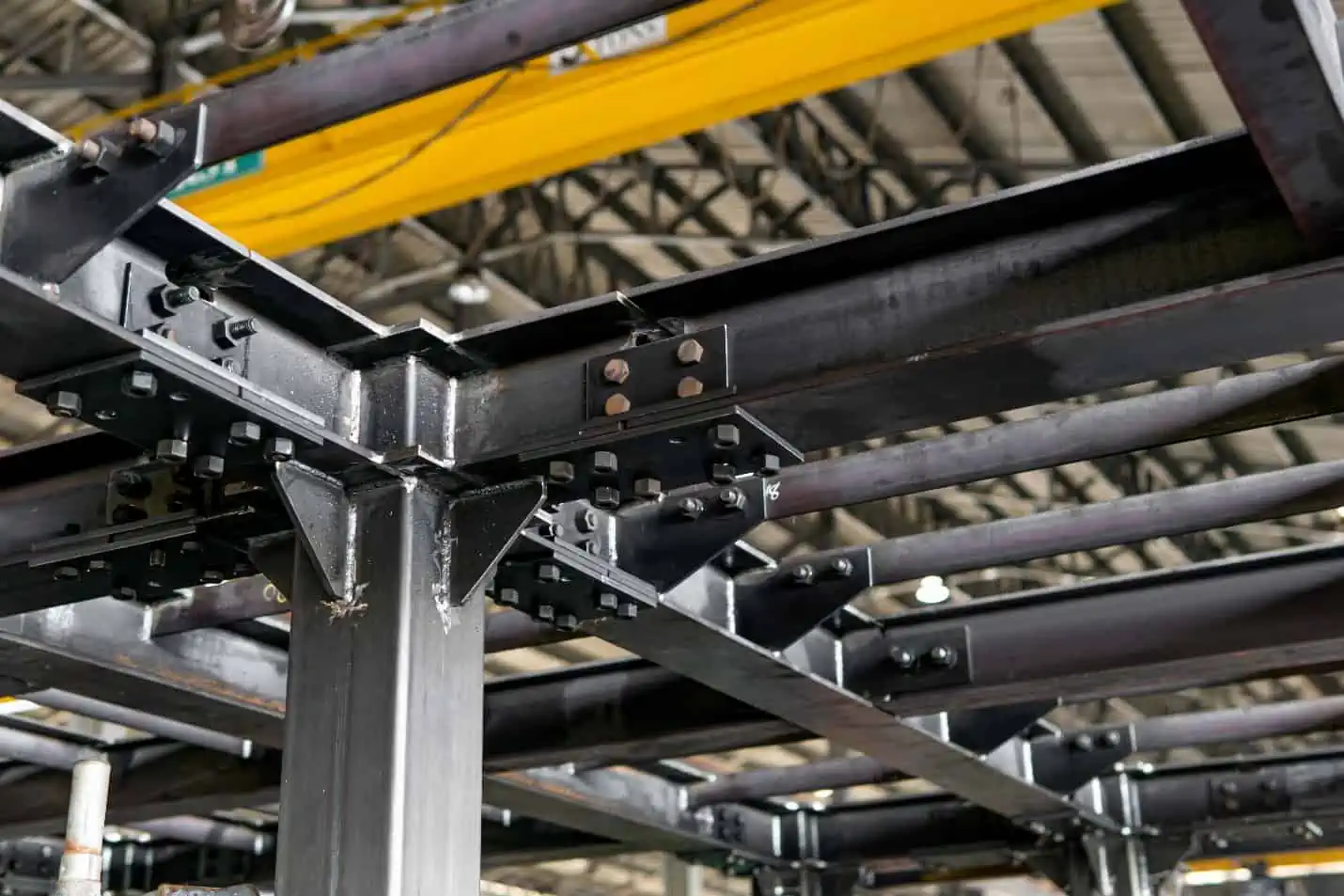
Understanding the shear center is vital as it plays a significant role in the stability and performance of beams and other structural components under various loads. When designing a beam, engineers must take into account the shear center to ensure the structural member can efficiently carry the load without experiencing twisting or other undesired deformations.
This is especially important in beams with thin-walled open cross-section like angles and T-beams. Since these types of beams are torsionally very weak, it is important to locate their shear center and consider the effect of twisting during the design process.
Determining the Shear Center
Symmetric Sections
In symmetric sections, the shear center always lies on the axis of symmetry. If there are two or more axes of symmetry, then the shear center is located at the point of intersection between the axes of symmetry, as shown in the diagram below.
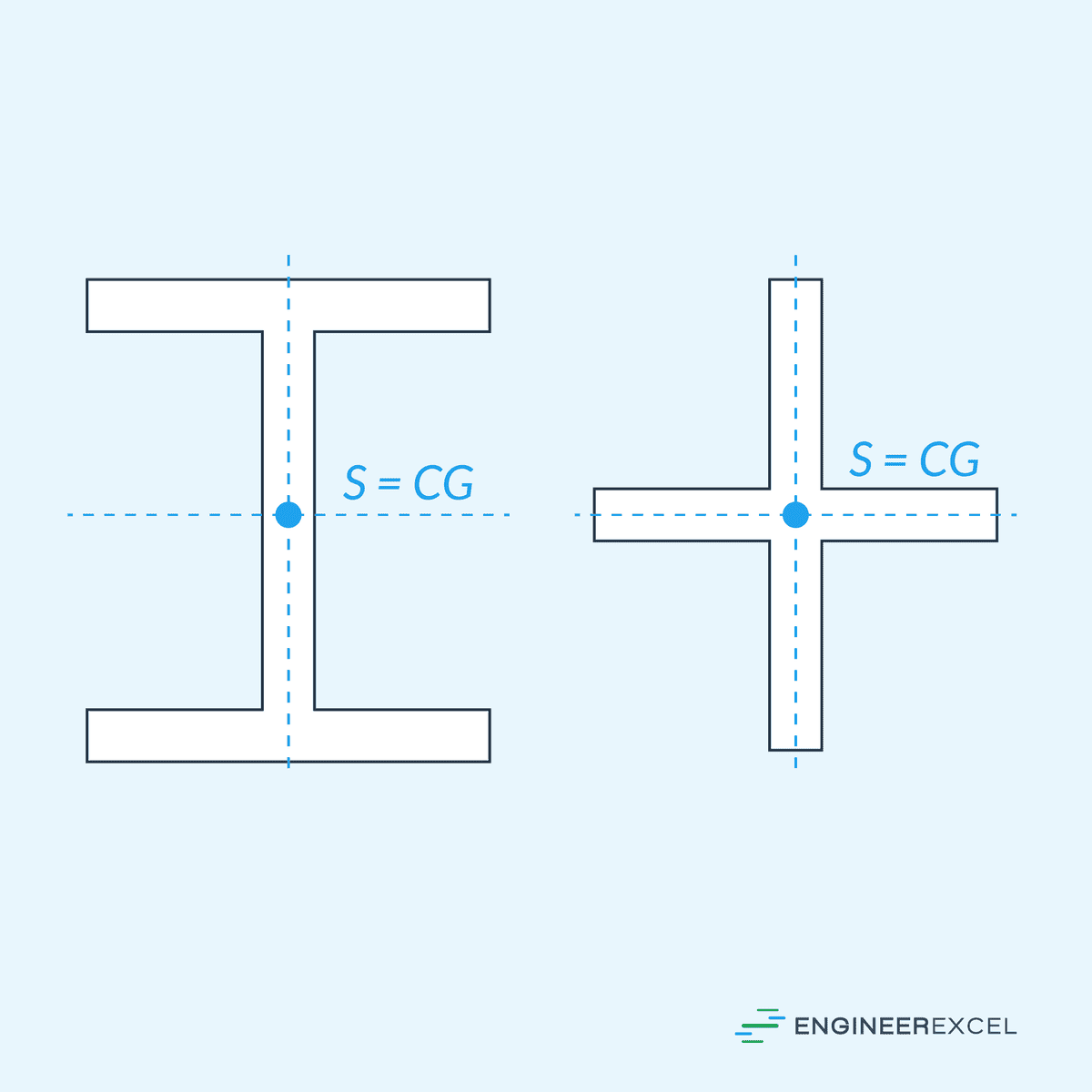
In this case, the shear center coincides with the centroid of the cross-section.
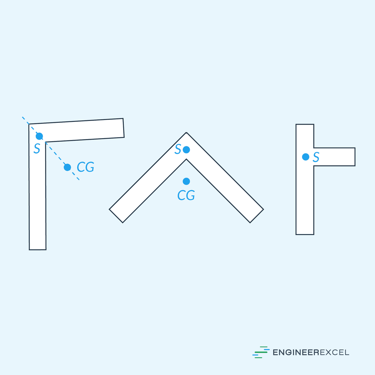
Angular Sections
If a section is made of two narrow rectangles, then the shear center lies on the junction of the rectangles, as shown in the diagram below.
Thin-Walled Open Sections
For unsymmetric open sections, determining the location of the shear center is a bit more complex. To illustrate, consider the diagram of a thin-walled open section below.
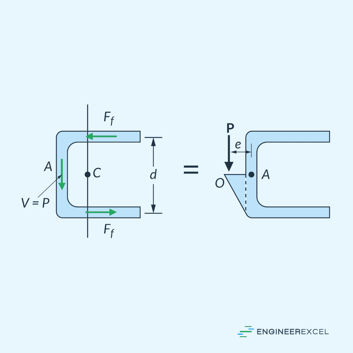
The location of the shear center can be determined by summing the moments of the shear-flow resultants about an arbitrary point A, and then equating this to a moment of a transverse load P applied at a distance e from point A. By calculating the distance e, we can determine the location of the shear center at point O.
As shown in the above example, the location of the shear center does not necessarily have to be within the structural member.
For more intricate geometries or in applications involving non-uniform material, more advanced methods, like numerical direct stiffness methods or finite element analysis can be used to locate the shear center. This approach involves forming an element mesh for the member and applying appropriate boundary conditions, followed by the evaluation of loadings and response.
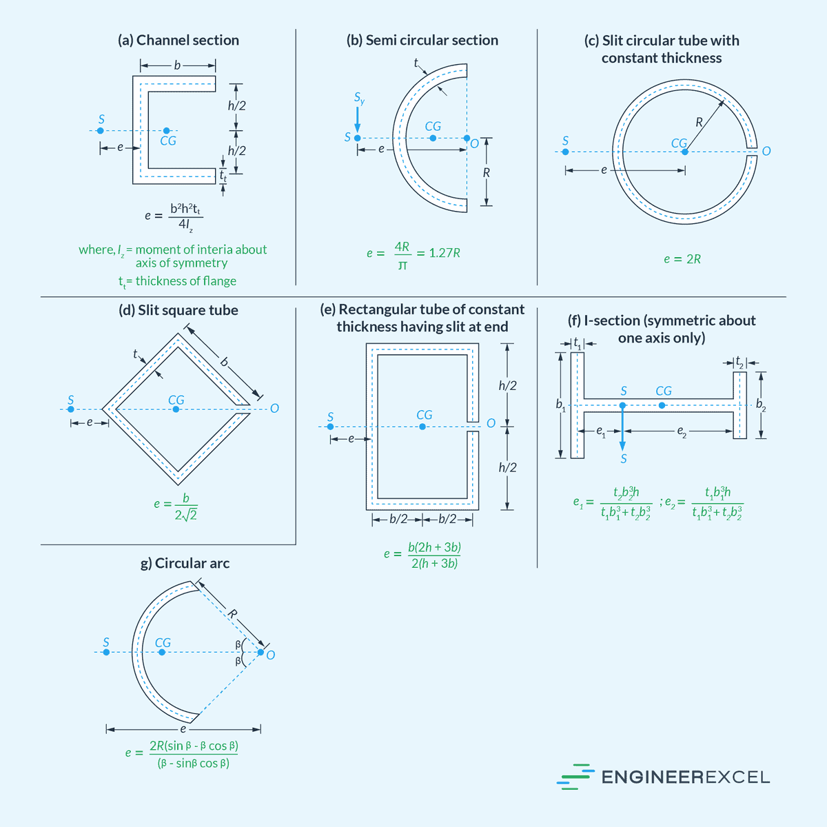
Shear Center of Common Sections
Design handbooks often list the formulas for determining the location of the shear center for a variety of commonly used beams having thin-walled cross sections. The table below lists some of these, including channel section, semi-circular section, slit circular tube, slit square tube, slit rectangular tube, I-section, and circular arc.