
A prismatic beam is a structural element with a consistent cross-sectional shape along its entire length. This is commonly used for load-carrying applications due to its consistent material properties, allowing for easier prediction and analysis of behavior under various loading conditions.

In this article, we will discuss the key fundamentals and design considerations of prismatic beams, including their properties, differences from non-prismatic beams, design parameters, and fabrication methods.
What is a Prismatic Beam?
A prismatic beam is a type of structural element that has a constant cross-sectional shape along its entire length. Common cross-sectional shapes include rectangular, I-shaped, T-shaped, and circular, among others. Each shape offers specific advantages depending on the application of the beam within a structure.
In engineering practice, prismatic beams are often used for load-carrying applications. Due to their constant cross-section, the material properties, such as modulus of elasticity and moment of inertia, remain consistent along the length of the beam. This allows engineers to more easily predict and analyze the behavior of these structural elements under various loading conditions.

Elevate Your Engineering With Excel
Advance in Excel with engineering-focused training that equips you with the skills to streamline projects and accelerate your career.
Moreover, prismatic beams can be made of various materials, including steel, concrete, and wood. The choice of materials depends on factors such as structural requirements, environmental conditions, and economic considerations. It is essential to select the appropriate material and cross-sectional shape to ensure the desired performance of a prismatic beam in a particular application.
It should be noted that while the analysis of prismatic beams is relatively simple, engineers must also consider additional factors such as boundary conditions, support conditions, and the presence of shear stresses. Proper assessment of these aspects contributes to a comprehensive understanding of the behavior of prismatic beams in different scenarios.
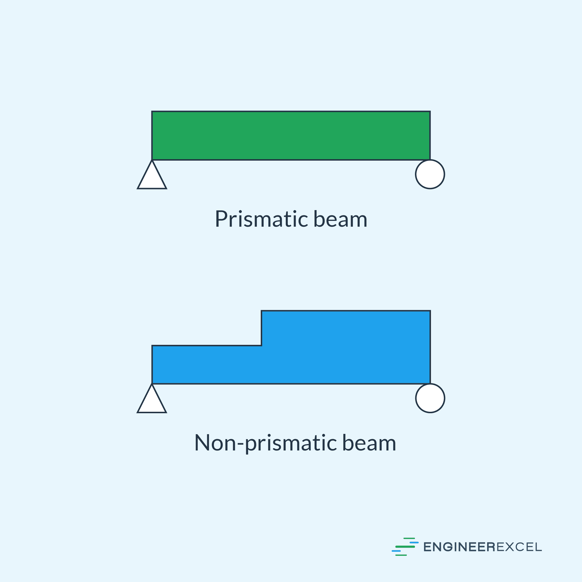
Prismatic vs Non-Prismatic Beams
Prismatic and non-prismatic beams are two categories that classify beams based on their cross-sectional properties. A prismatic beam refers to a beam with a constant cross-sectional shape and size throughout its length. In contrast, a non-prismatic beam exhibits a varying cross-sectional shape or size along its length.
Prismatic beams are more straightforward to analyze as they maintain uniform properties such as area, moment of inertia, and stiffness. Consequently, the governing equations for prismatic beams are well-established and simpler to apply. In engineering practice, prismatic beams can be found in various structures, such as beams in buildings, railway tracks, and bridge girders.
Non-prismatic beams, on the other hand, require more complex analysis due to their varying cross-sectional properties. These variations may result from design optimization, structural requirements, or manufacturing constraints. Some examples of non-prismatic beams include tapered beams, beams with haunches, and beams with flange thickening.
There are key differences between prismatic and non-prismatic beams when analyzing their behavior under loads. One aspect to consider is the deflection of the beam.
For prismatic beams, the deflection typically follows a predefined shape, such as parabolic or cubic, depending on the kinds of loads and boundary conditions. In contrast, non-prismatic beams may experience deflections that do not adhere to common shapes due to their varying stiffness along the length.
Another aspect to consider is the distribution of shear forces and bending moments. Prismatic beams typically exhibit a linear variation of shear force and a parabolic or cubic variation of bending moments along their length. On the other hand, non-prismatic beams may present more irregular distributions due to their varying cross-sectional properties.
Prismatic Beam Design
In designing prismatic beams, it is usually unnecessary to graph the stress behavior of the beam. Instead, the crucial aspect is to ensure that the actual bending stress and shear stress in the beam do not exceed the allowable bending and shear stress for the material. This can be evaluated using two parameters: section modulus and allowable shear stress.
Section Modulus
The section modulus is a geometric property of a beam cross-section, defined as follows:
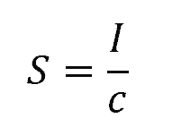
Where:
- S = section modulus [m3]
- I = moment of inertia [m4]
- c = distance from the neutral axis to the extreme fiber [m]
A higher section modulus indicates a beam with greater resistance to bending. Since beams usually have long spans, which lead to substantial internal moments, the typical process is to first focus on designing for bending before evaluating the shear strength.
Given a specific beam material and a maximum bending moment, the required section modulus for a beam can be calculated using the following formula:
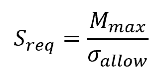
Where:
- Sreq = required section modulus [m3]
- Mmax = maximum bending moment along the beam [N-m]
- σallow = allowable bending stress for the beam material [Pa]
Once the required section modulus is calculated, the dimensions of the beam can be determined from the corresponding moment of inertia. This depends on the shape of the cross section.
However, in practice, there are handbooks that list the section modulus of standard shapes available
from manufacturers. By selecting an optimal cross-sectional shape and dimensions, an engineer ensures the beam meets the required bending strength performance.
Allowable Shear Stress
Once the beam has been selected based on the section modulus, it is important to confirm that the allowable shear stress is not exceeded. This can be done using the shear stress formula as follows:
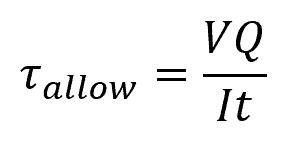
Where:
- τallow = allowable shear stress for the beam material [Pa]
- V = shearing force [N]
- Q = first moment of area [m3]
- I = moment of inertia [m4]
- t = beam thickness [m]
Prismatic Beam Fabrication
Prismatic beams can be made of various materials such as steel, wood, or built-up sections. Fabrication of these beams requires specific processes tailored to the chosen material and intended application.
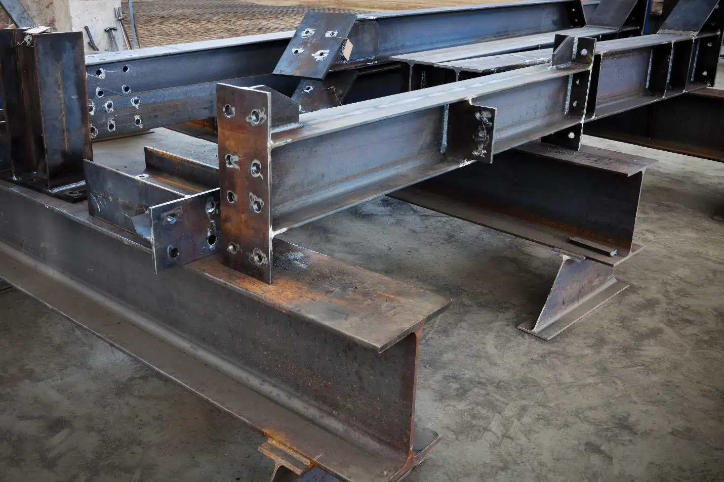
For steel sections, prismatic beams are typically formed through a series of rolling processes. Steel billets are initially heated and then passed through rollers, which progressively compress and shape the material into the desired cross-sectional profile. Profiles such as I-beams, H-beams, and T-beams, for example, can be produced via this technique.
Wood sections are produced by cutting and shaping lumber harvested from suitable tree species. Depending on wood quality and the desired beam profile, different manufacturing processes may be employed, such as sawing, planing, or gluing together multiple smaller sections. The choice of treatment, like pressure treatment and impregnation with preservatives, is important to enhance the durability and resistance to decay of wooden prismatic beams.
When it comes to built-up sections, these are created by assembling multiple components together, often using different materials to improve overall strength and optimize the weight-to-strength ratio. Common built-up beams include:
- Plate girders: Composed of steel plates welded or bolted together in a series of flanges and webs.
- Trussed beams: A combination of steel angles and plates connected by welding or bolting to form a truss-like structure.
- Box beams: Square or rectangular hollow sections formed through welding or bolting separate individual plates.
During fabrication, it is crucial to follow appropriate welding or bolting procedures to ensure strong and reliable connections between components. Proper inspection and non-destructive testing methods, such as ultrasonic testing, magnetic particle, and dye penetrant, should be employed to assess the quality of the connections and overall structural integrity.