
A cantilever beam is a rigid structural element that is fixed at one end and free at the other. This unique configuration allows cantilever beams to be used in overhanging structures without external bracing, creating an unobstructed space below the beam.
In this article, we will discuss the characteristics, applications, and calculations related to cantilever beams.
What is a Cantilever Beam?
Beams are horizontal members designed to carry and distribute loads, such as the weight of floors, roofs, or other structural components. They can come in various shapes, sizes, and configurations, each tailored to specific applications and conditions. One popular beam configuration is the cantilever beam.
A cantilever beam is characterized by one end being securely fixed while the other end can extend freely without any additional support, as shown in the diagram below. In this configuration, the fixed end is typically anchored to a rigid support, such as a wall or column. Because of this unique characteristic, cantilever beams can resist bending, deflection, and torsion in response to loads.

Elevate Your Engineering With Excel
Advance in Excel with engineering-focused training that equips you with the skills to streamline projects and accelerate your career.
The fixed end is subjected to zero movement. This means that there is neither translation nor rotation that can occur. However, the elastic properties of the beam material allow for the ability to stretch and bend when a load is applied and removed.
Because of the lack of support at one end, cantilever beams display a noticeable deflection under load compared to other beam configurations. This can alter their shape significantly, depending on factors such as the beam material, its dimensions, and the magnitude of the applied load.
Applications of Cantilever Beams
One of the main advantages of cantilever beams is their ability to extend span without the need for supporting columns or structures in the middle of the span. This can be advantageous in situations where it’s important to maintain unobstructed space below the beam. By extending the beam from a single support point, there is minimal disruption to the navigation or traffic below.
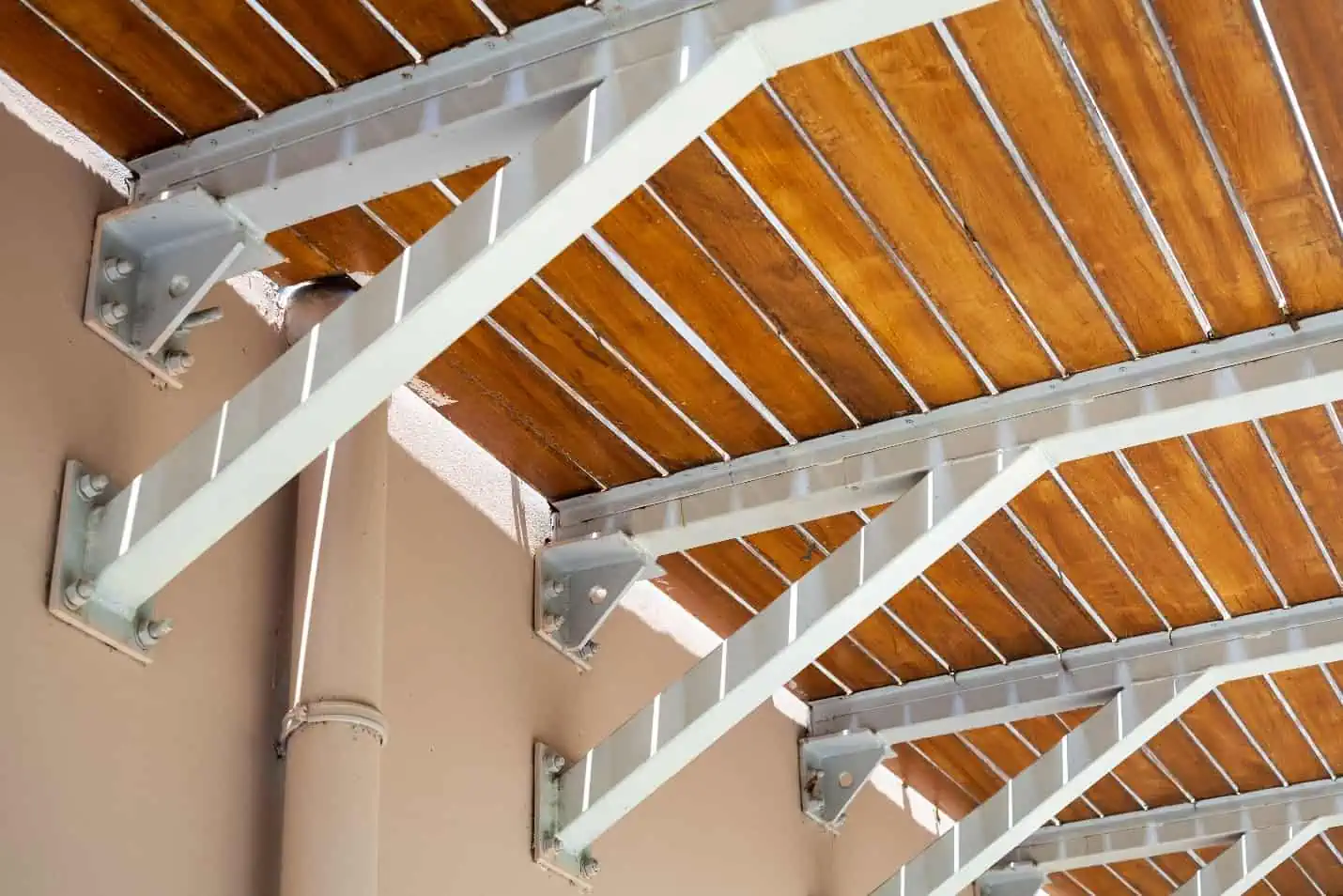
In building construction, for example, cantilever beams are frequently utilized for balconies, roofs, and frames, efficiently supporting the load while offering architectural flexibility. Additionally, they play an important role in the design of various bridge types, including cantilever, truss, and cable-stayed bridges, where they help evenly distribute the load along the bridge’s length.
Also, since cantilever beams are supported at only one end, they can more easily accommodate thermal expansion and ground movement. Changes in temperature can cause materials to expand or contract, and structures need to be able to handle these movements without causing damage. Cantilever beams, with their one-sided support, can allow for more flexibility in dealing with such movements.
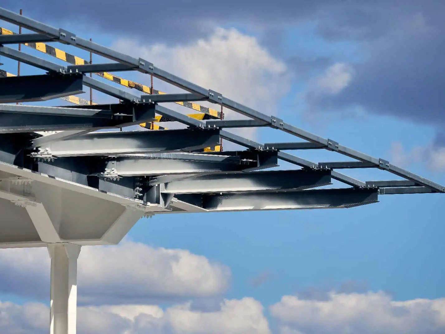
However, the disadvantage of relying on only one support is that cantilever beams, particularly at the arms, must be massive to bear significant loads. To address this issue, truss construction is often employed.
Trusses are frameworks of interconnected members that efficiently distribute loads, minimizing the material required while maintaining structural integrity. The use of truss construction in larger applications helps reduce the overall weight of the structure, making it a practical solution to overcome the limitations associated with the massiveness of cantilever beams.
Cantilever Beam Calculations
Cantilever Beam Support Reactions
The support reactions on the fixed end of a cantilever beam depend on the direction, configuration, and magnitude of the applied load. However, the typical support reactions are a vertical force, a horizontal force, and a moment at the fixed end, as shown in the diagram below.
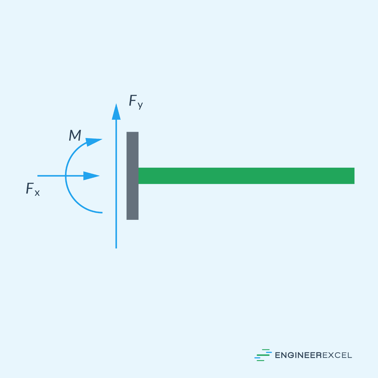
The values of these reactions can be determined using equilibrium equations, considering the forces and moments acting on the beam. The horizontal force is usually assumed to be zero unless there is a horizontal load applied.
Once the support reactions are determined, the shear and bending moment can be calculated along the length of the beam.
Cantilever Beam Deflection
Deflection refers to the displacement of a beam resulting from applied loads. Cantilever beams, in general, tend to experience greater deflection compared to other beam configurations due to being supported only at one end.
Various methods can be employed to calculate this deflection, which is influenced by the specific loading applied to the beam. However, predetermined formulas exist for determining the maximum deflection under common loading configurations for cantilever beams.
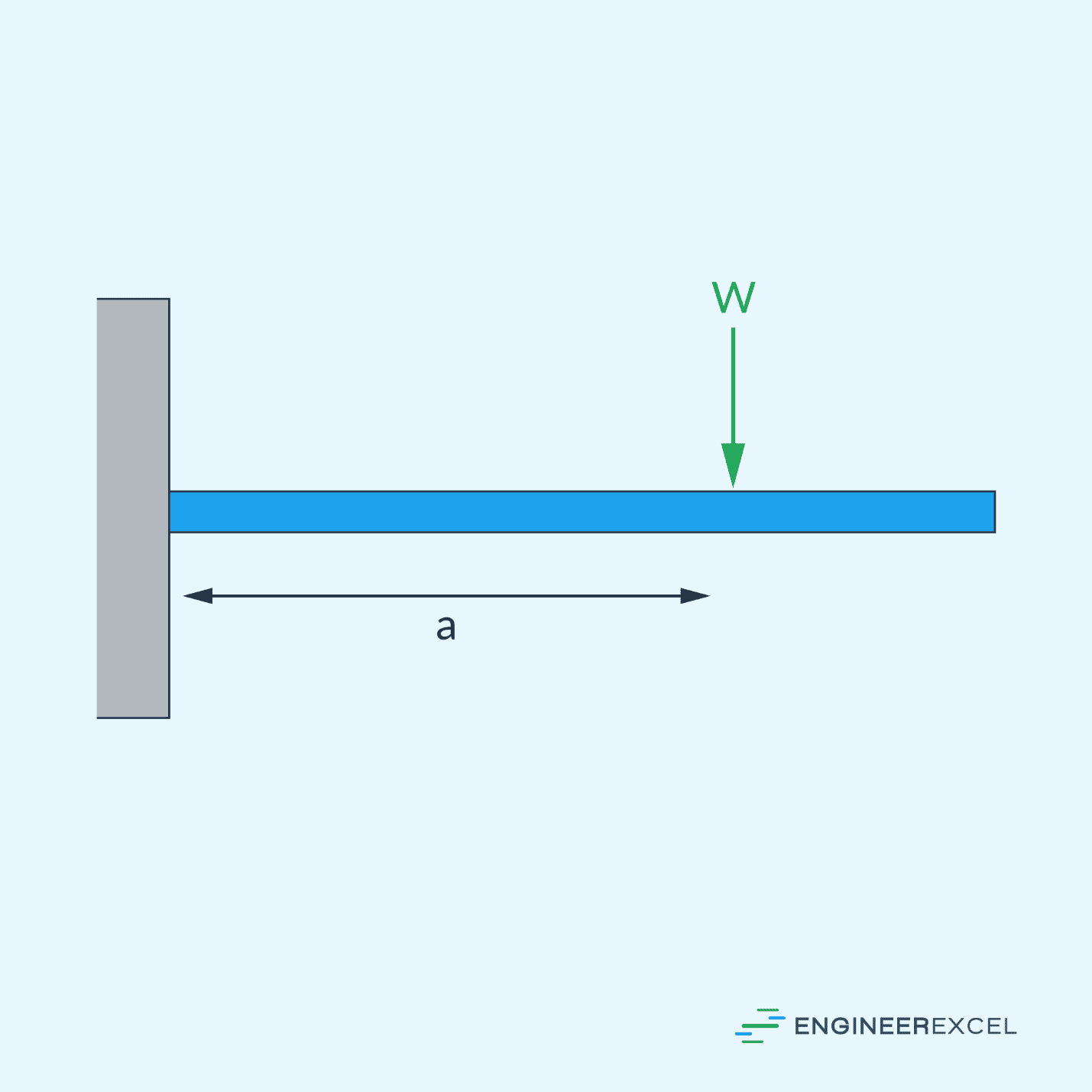
For example, for a cantilever beam with a point load applied, shown in the diagram above, the maximum deflection can be calculated using the following formula:
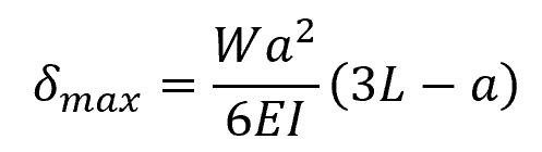
Where:
- Δmax = maximum deflection [m]
- W = applied point load [N]
- a = distance of the point load from the fixed end [m]
- L = length of the beam [m]
- E = Young’s modulus of the beam material [Pa]
- I = moment of inertia of the beam [m4]
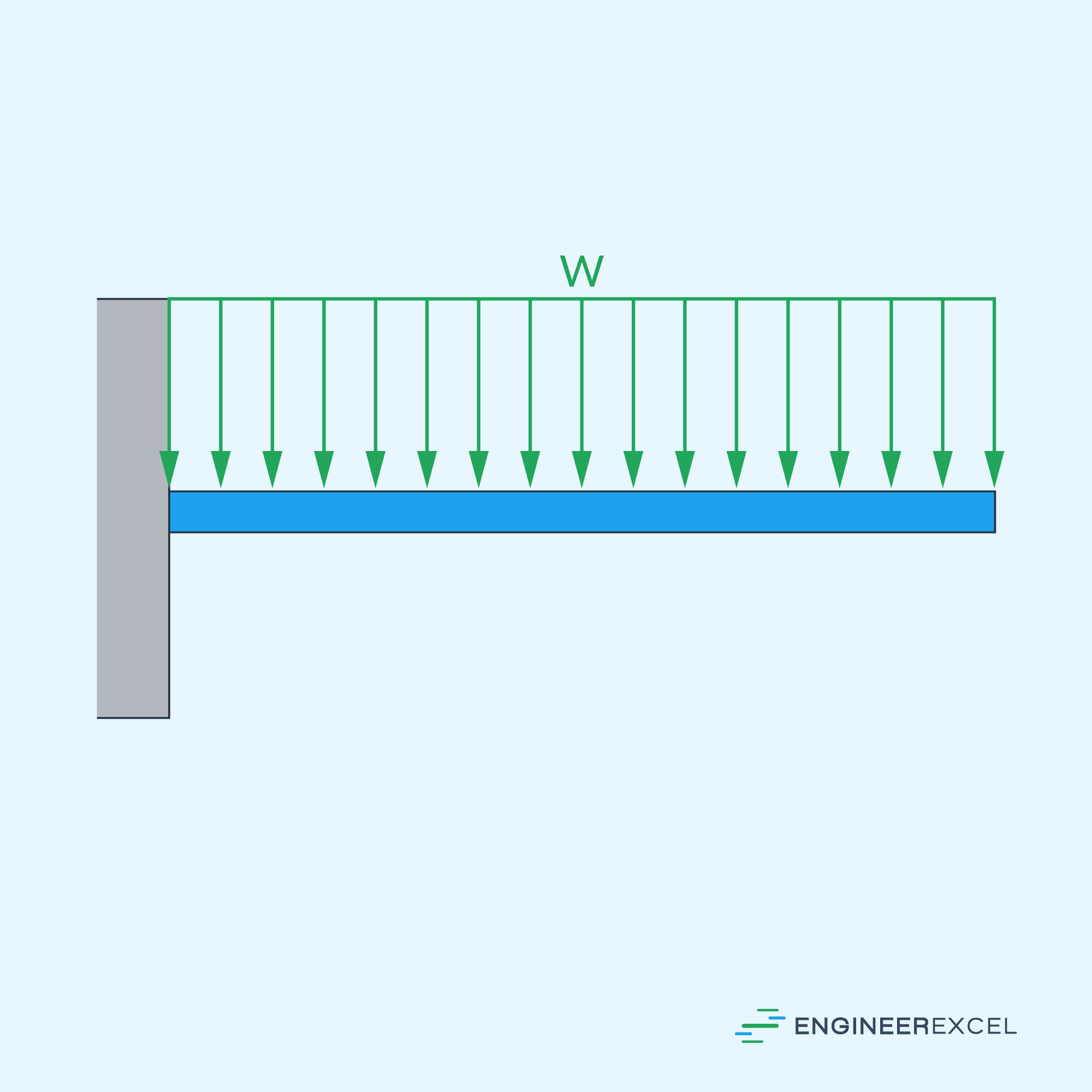
On the other hand, for a cantilever beam with a uniformly distributed load applied, shown above, the formula for the maximum deflection is:
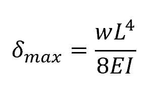
Where:
- w = distributed load [N/m]