FEATURED Stress and Strain Transformations RESOURCES
[no_toc]
Mohr-Coulomb Failure Criterion: A Key to Brittle Material Failure Analysis
How Does a Strain Gauge Work: Exploring the Fundamentals and Applications

Understanding Principal Strains: The Foundation of Deformation Analysis
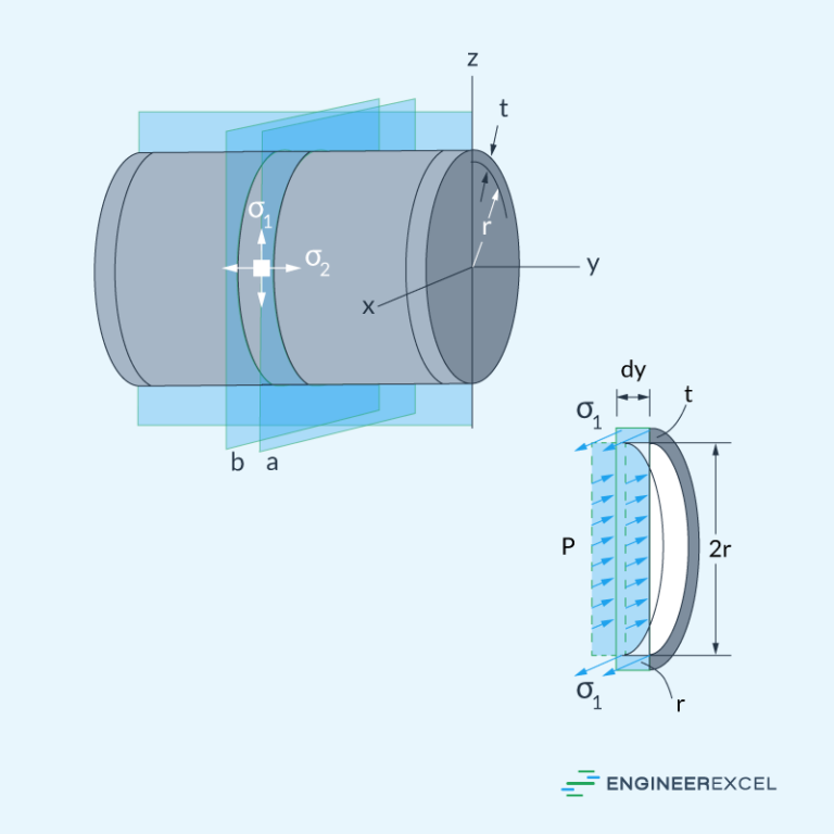
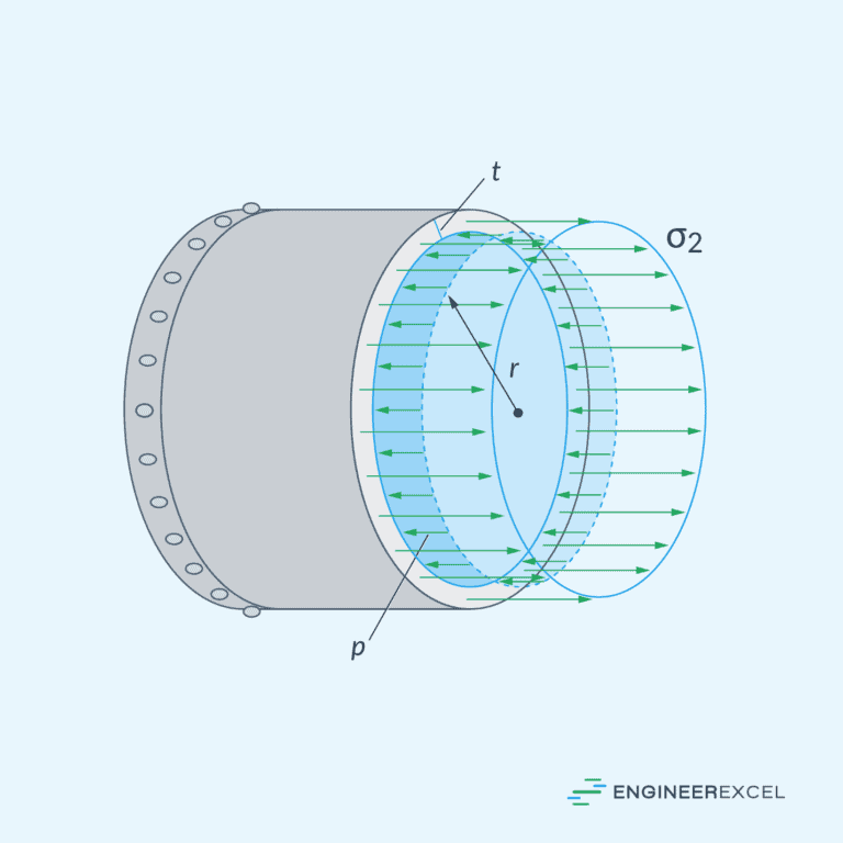
Hoop Stress Derivation Explained
Plane Stress Mechanics: An Overview
Mohr’s Circle Equations A Convenient Tool for Stress and Strain Transformations
Understanding Longitudinal Stress in Cylindrical Vessels
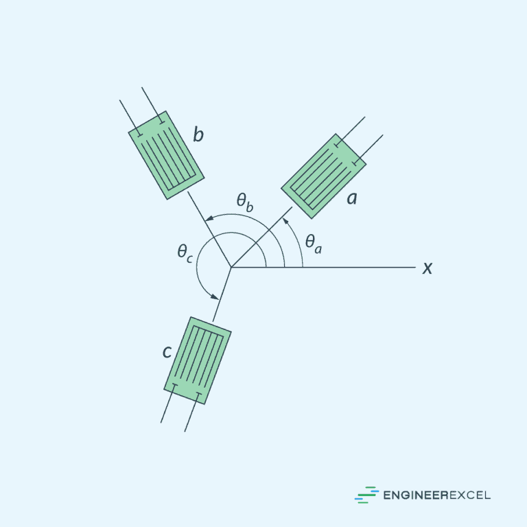
Rosette Strain Gauge and Its Role in Strain Analysis
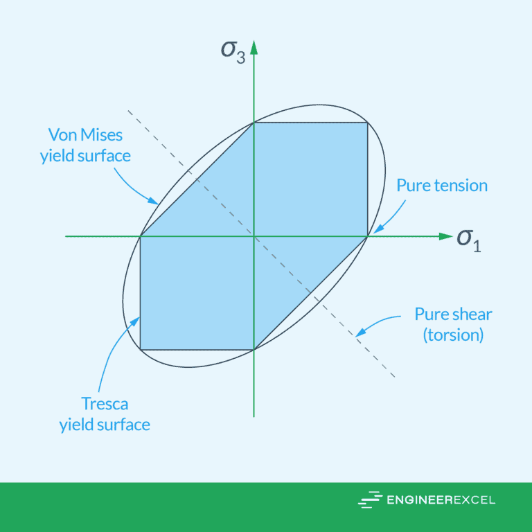
Tresca Yield Criterion: Theory of Failure in Ductile Materials
Plane Strain in Mechanics of Materials: An Overview
Maximum Shear Strain: Calculation and Impact in Engineering Analysis
Von Mises Yield Criterion: A Key to Predicting Material Failure

Principal Stresses and Their Importance in Structural Calculations

Maximum Shear Stress Theory Explained
Strain Transformation Equations: Understanding the Mechanics
Stress and strain transformation is the process of expressing the components of stress and strain in a material under different orientations of the coordinate system. This helps to characterize how the material responds to varying loading directions and provides valuable insights into its mechanical behavior. In this article, we will discuss the fundamentals of stress and strain transformation, including the concepts of plane stress and plane strain, principal stresses and strains, maximum shear stress and strain, and the use of Mohr’s Circle.
Fundamentals of Stress and Strain
Stress and strain are fundamental concepts in engineering that describe the internal loads within the body. Stress is a measure of the internal resistance of a material to deformation, while strain quantifies the deformation caused by the applied forces. Understanding the relationship between these two is important for the design and analysis of components and structures subjected to various loads.
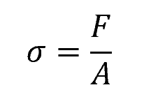
Mathematically, stress is defined as the force per unit area acting on a plane passing through a point of interest in a material:

Elevate Your Engineering With Excel
Advance in Excel with engineering-focused training that equips you with the skills to streamline projects and accelerate your career.
Where:
- σ = stress [Pa]
- F = applied force [N]
- A = area [m2]
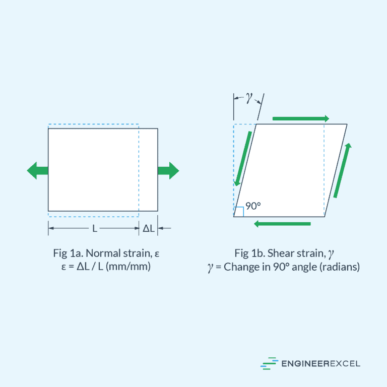
Stress can be classified into normal stress (σ), which acts perpendicular to the plane, and shear stress (τ), which acts parallel to the plane.
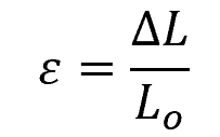
Strain, on the other hand, is a measure of the relative deformation of the material. It is dimensionless and represented by ε. For small deformations, strain can be expressed as:
Where:
- ε = strain [unitless]
- ΔL = change in length [m]
- L₀ = initial length [m]
Strain can also be classified into normal strain (ε) and shear strain (γ).
Plane Stress and Plane Strain
In a three-dimensional object, the general stress and strain states at a point can be described by six independent normal and shear stress and strain components, which act on the six faces of a material element. However, these general states are not commonly encountered in engineering practice. Instead, engineers often simplify the loadings on a body so that the stress in an element can be analyzed in a single plane.
When this happens, the material is said to be under plane stress and/or plane strain. For instance, if there is no load on a particular surface of a body, then the normal and shear stress components will be zero on the face of an element located on this surface. As a result, the corresponding stress components on the opposite face will also be zero, and the material at that point will be under plane stress.
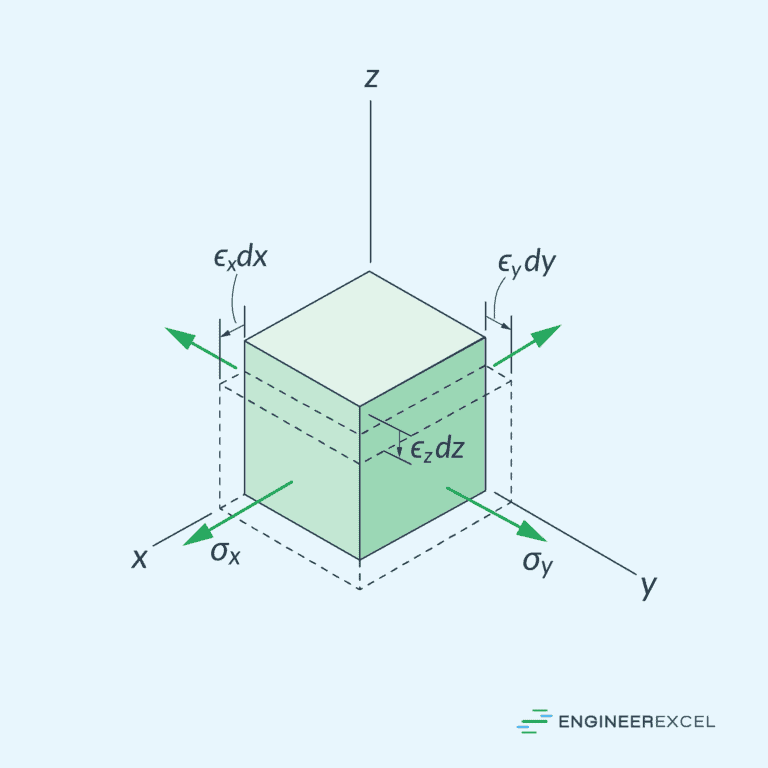
Plane stress is characterized by two normal stress components and one shear stress component, as shown in the diagram below.
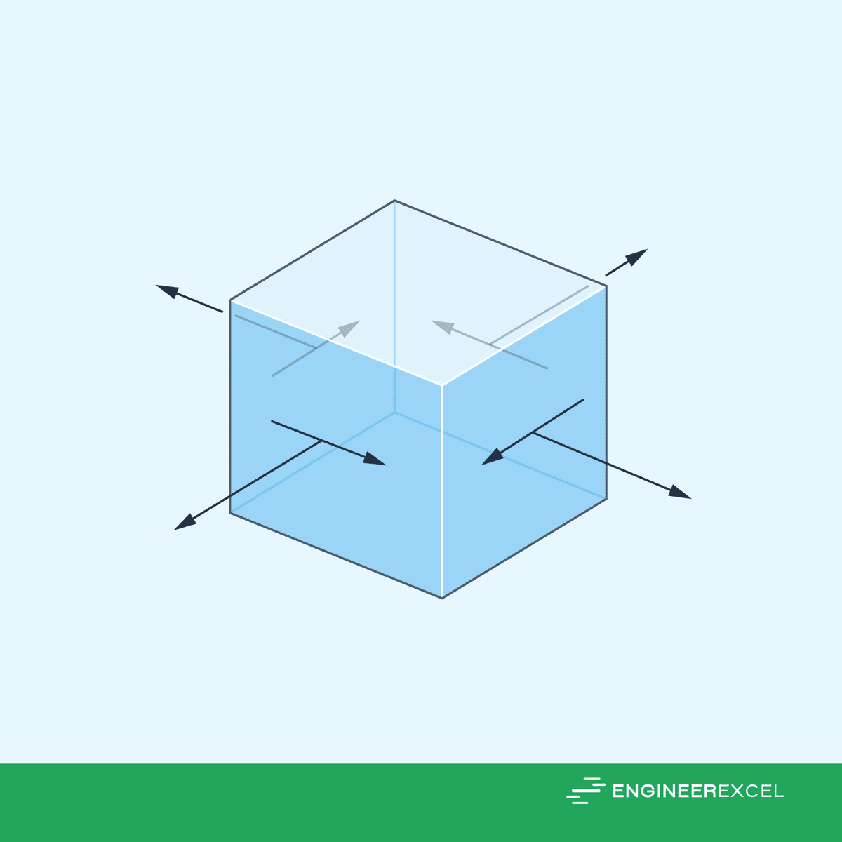
In the same manner, plane strain is characterized by two normal strain components and one shear strain component.
Stress Transformation
Engineers often encounter situations where stresses act in different directions on a component. In such cases, it is necessary to perform stress transformations to evaluate the material’s response.
Stress Transformation Equations
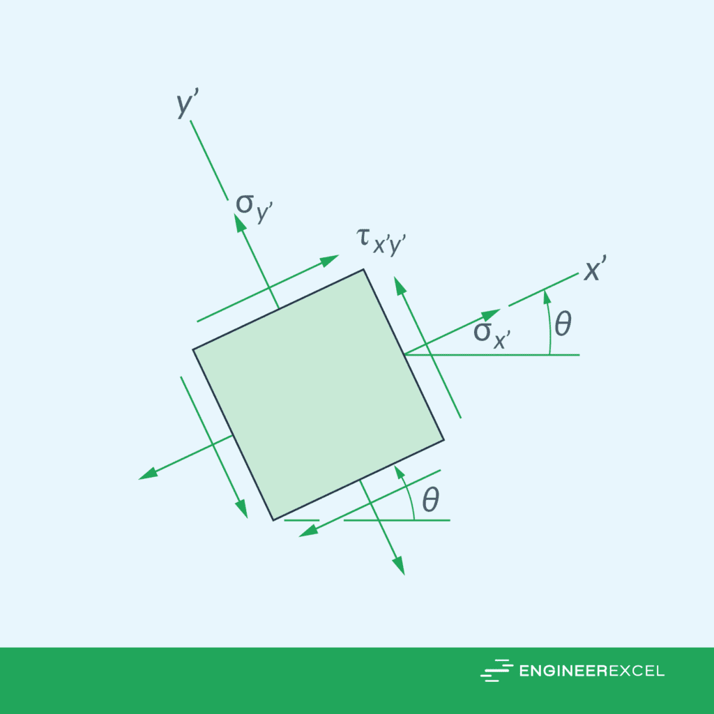
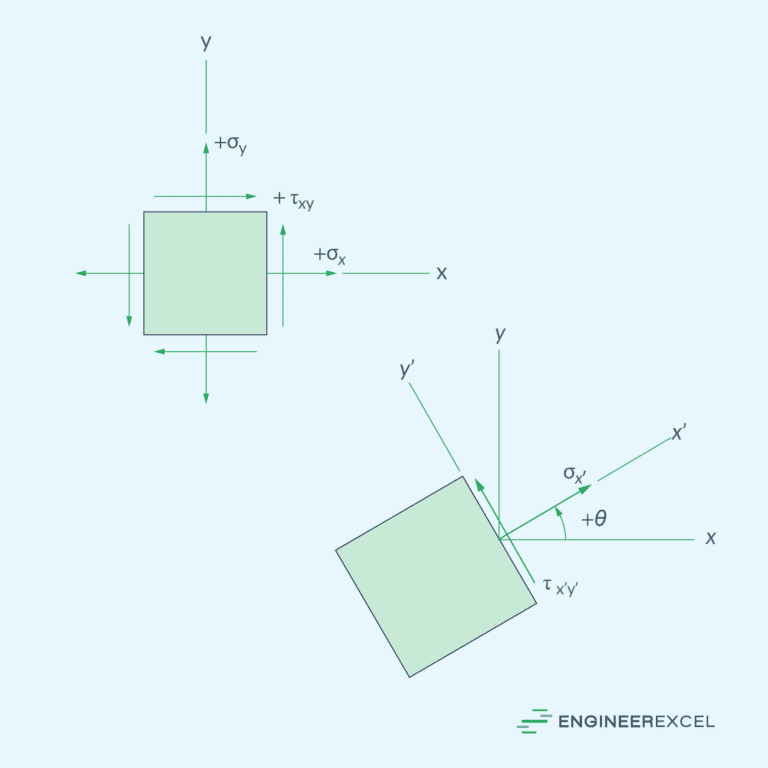
Stress transformation equations are mathematical expressions that describe how stress components (normal and shear stress) change when the coordinate system rotates, as shown in the diagram below.

In the case of plane stress, the stress transformation equations are given by:
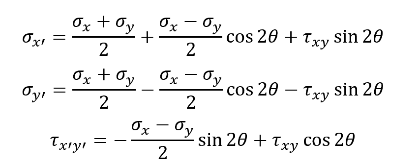
Where:
- σx, σy = normal stress components [Pa]
- τxy = shear stress component [Pa]
- σx’, σy’ = transformed normal stress components [Pa]
- τx’y’ = transformed shear stress component [Pa]
- θ = angle between the original and the transformed axes [rad]
Principal Stresses
Using stress transformation, the maximum and minimum normal stress components of an element can be determined. These are called principal stresses, which can be calculated using the following formula:
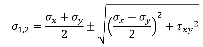
Where:
- σ1,2 = maximum and minimum principal stresses [Pa]
The orientation of the principal plane at which the principal stresses occur is given by:
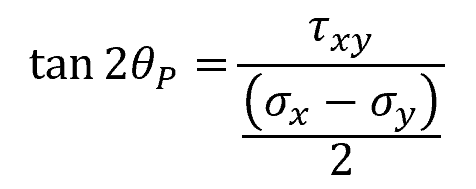
Where:
- θP = angle of the principal plane with respect to the original axis [rad]
Maximum Shear Stress
Similar to principal stresses, the maximum shear stress can also be determined using stress transformation equations. This can be done by finding the angle θ that maximizes the transformed shear stress component (τx’y’). The maximum shear stress can be calculated using the formula:
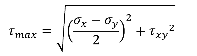
Where:
- τmax = maximum shear stress [Pa]
The orientation of the plane of maximum shear stress is 45° from the position of the principal plane.
Strain Transformation
Similar to stress transformation, strain components can also be transformed to a different coordinate system.
Strain Transformation Equations
To perform strain transformation, the following equations can be used:
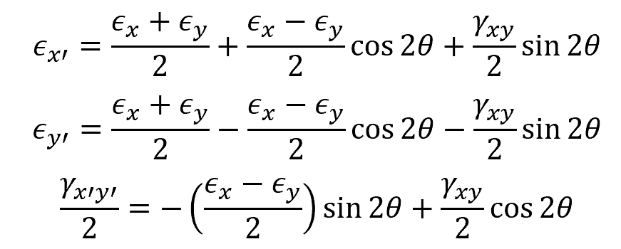
Where:
- ϵx, ϵy = normal strain components [unitless]
- γxy = shear strain component [rad]
- ϵx’, ϵy’= transformed normal strain components[unitless]
- γx’y’ = transformed shear strain component [rad]
- θ = angle between the original and the transformed axes[rad]
Principal Strains
Using strain transformation, the maximum and minimum normal strain components, called principal strains, of an element can be determined. To calculate the principal strains, use the following formula:
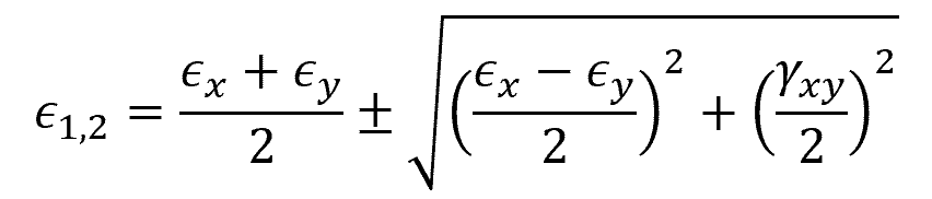
Where:
- ϵ1,2 = maximum and minimum principal strains [unitless]
The orientation of the plane at which the principal strains occur is given by:
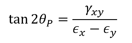
Where:
- θP = angle of the principal plane with respect to the original axis [rad]
Maximum Shear Strain
The maximum in-plane shear strain is the largest value of shear strain that occurs in a material. It is of particular interest in engineering analysis because materials often fail under high shear stress. To find the maximum shear strain, use the following formula:
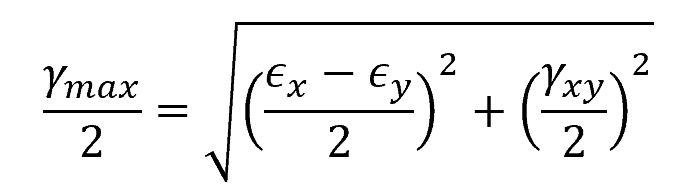
Where:
- γmax = maximum in-plane shear strain [rad]
This occurs at an orientation 45 degrees from the plane of principal strains. There is also an associated average normal strain that occurs in this orientation, which can be calculated using the formula:
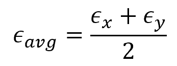
Where:
- ϵavg = average normal strain [unitless]
Mohr’s Circle
As discussed above, stress and strain transformation can generally be done using mathematical equations. However, it is often more convenient to visualize the process using Mohr’s Circle.
Mohr’s Circle is a graphical representation used for the transformation of stresses and strains in two-dimensional systems. It offers valuable insight into the relationships between normal and shear components, allowing for the visualization of the maximum and minimum stress and strain components acting on an element.
Mohr’s Circle Equations for Plane Stress
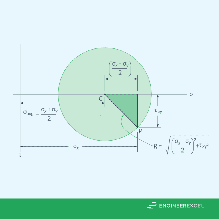
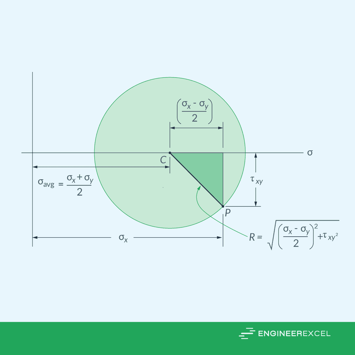
For plane stress, the first step in constructing Mohr’s Circle is to determine the center of the circle. This represents the average normal stress and it can be computed using the formula:
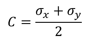
Where:
- C = center of the circle [Pa]
Next, the radius of the circle, which corresponds to the maximum shear stress, can be found using the formula:
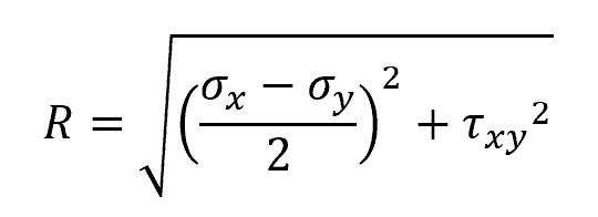
Where:
Using the calculated values for C and R, the Mohr’s Circle can be plotted, as shown in the diagram below. The horizontal axis represents normal stresses, while the vertical axis represents shear stresses.
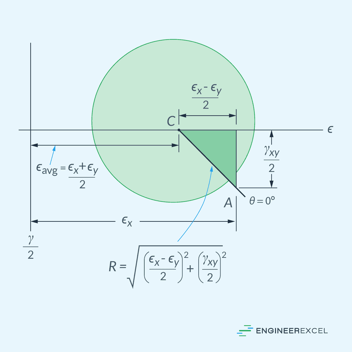
Mohr’s Circle for Plane Strain
In a similar manner, Mohr’s Circle can be used for plane strain. In this case, the center of the circle, which corresponds to the average normal strain, can be computed using the formula:
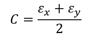
Where:
- C = center of the circle [unitless]
Then, the radius of the circle can be found using the formula:
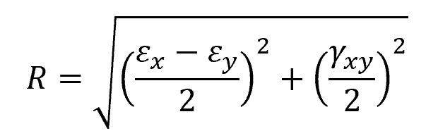
Where:
- R = radius of the circle [unitless]
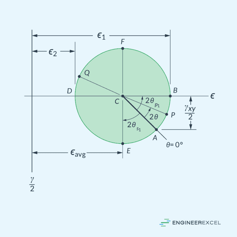
Now, we can plot the Mohr’s Circle for plane strain as shown in the diagram below. The horizontal axis represents normal strain, while the vertical axis represents half of the shear strain.