
Understanding the maximum and minimum stresses acting on a material is important in identifying potential failure points and optimizing designs in engineering.

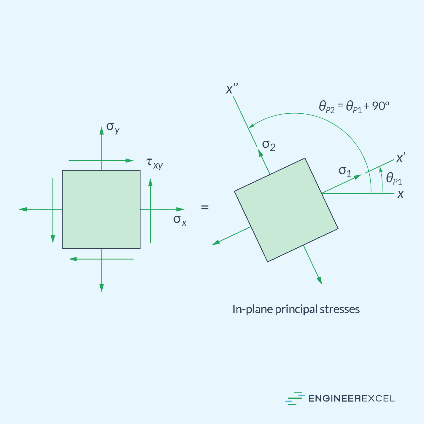
The maximum and minimum in-plane normal stresses that occur at a particular point are called principal stresses, and the planes at which they occur are called the principal planes of stress.
What Are Principal Stresses
In general, the magnitude of plane stresses depends on the angle of inclination of the planes on which they act. Therefore, there is a specific plane orientation where the maximum and minimum stresses occur.
The maximum and minimum in-plane normal stresses that occur at a particular point are called principal stresses, and the planes at which they occur are called the principal planes of stress. As shown in the diagram below, the maximum and minimum principal planes are 90 degrees apart. Along these planes, there is no shear stress that occurs.

Elevate Your Engineering With Excel
Advance in Excel with engineering-focused training that equips you with the skills to streamline projects and accelerate your career.
Understanding the principal stresses and principal planes are important in engineering design because they provide key insights into the state of stress within a material. Principal stresses represent the maximum and minimum magnitudes of stress experienced at a point, revealing critical information about the material’s strength and potential failure points.
Knowing the principal planes helps engineers orient structures or components to minimize stress concentrations and optimize their performance. This knowledge is vital for designing safe and reliable structures, ensuring that materials are utilized efficiently, and preventing unexpected failures due to high stress concentrations or inappropriate material orientations.
Calculation of Principal Stresses
The equations used for calculating the principal stresses are derived using stress transformation equations. Given a general state of plane stress, represented by a combination of two normal-stress components (σx and σy) and one shear stress component (τxy), the orientation of the principal planes can be calculated using the following formula:
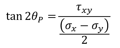
Where:
- θP = angle of the principal plane with respect to the original x axis [rad]
- τxy = shear stress component before stress transformation [Pa]
- σx = normal stress component along the x axis before stress transformation [Pa]
- σy = normal stress component along the y axis before stress transformation [Pa]
Note that the solution to this equation has two roots. This means that there are two possible values for θP, separated 90 degrees apart. One corresponds to the maximum principal plane, while the other corresponds to the minimum principal plane.
To obtain the magnitude of the principal stresses, the original normal stress components can be transformed into the principal planes using the following equation:
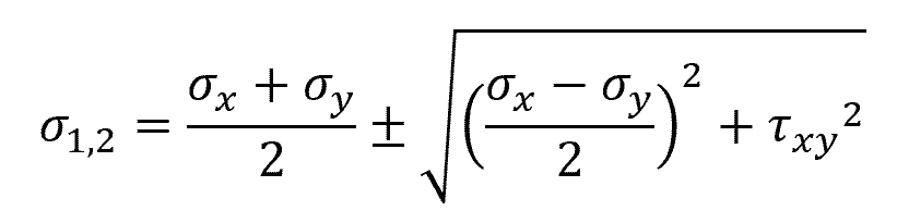
Where:
- σ1,2 = principal stresses [Pa]
Note that the solution to this equation also has two roots that correspond to the maximum and minimum principal stresses. In general, σ1 is denoted as the maximum principal stress, while σ2 is denoted as the minimum principal stress.
Determining Principal Stresses Using Mohr’s Circle
Mohr’s circle is a graphical method used to represent the state of stress at a particular point in a material. It is typically drawn on a set of axes, with the normal stress on one axis and the shear stress on the other.
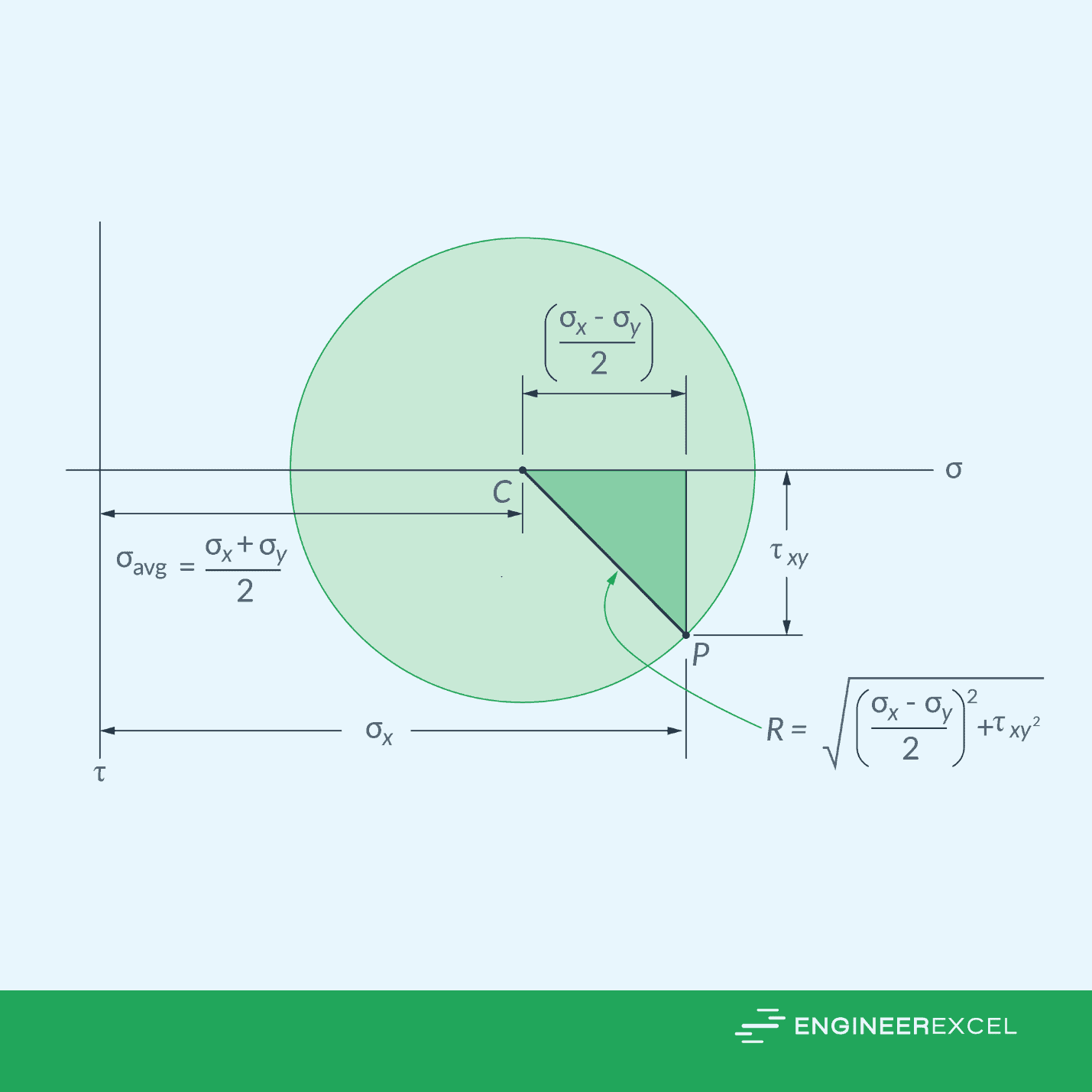
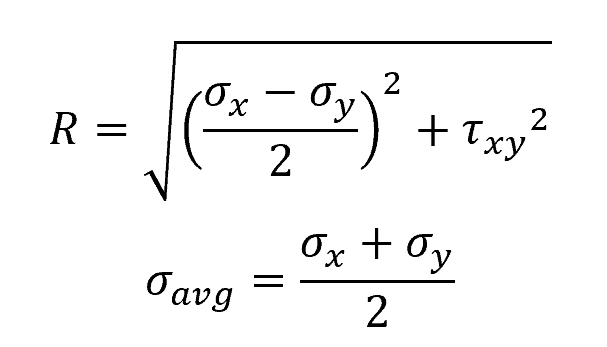
The coordinates of a point on the circle correspond to the normal and shear stresses acting on a particular plane within the material. The radius of the circle represents the maximum shear stress, and the center of the circle corresponds to the average normal stress. These can be calculated using the following formulas:
Where:
- R = radius of the circle, corresponding to the maximum shear stress [Pa]
- σavg = center of the circle, corresponding to the average normal stress [Pa]
Once the Mohr’s Circle is constructed, it can be used to determine the principal stresses and the orientation of the principal planes, as shown in the diagram below.
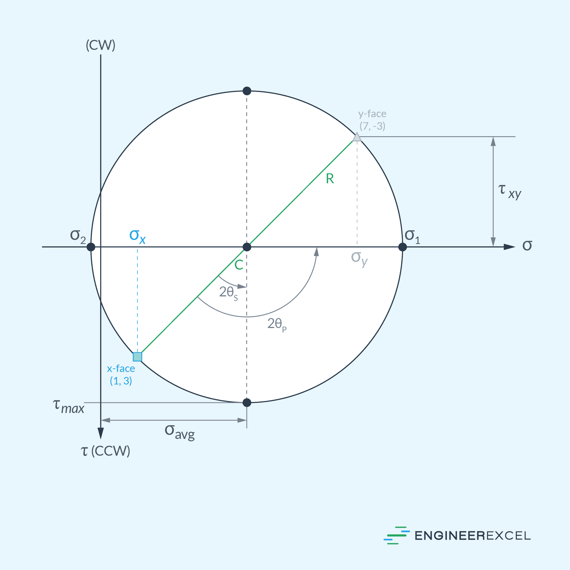
For a two-dimensional stress state, the principal stresses are located at the intersections of the Mohr’s Circle with the x-axis. The corresponding planes where these principal stresses act are at angles halfway between the angles of the Mohr’s Circle intersections with the x-axis.