
Plane stress refers to a state of stress that is limited to two dimensions, where all the stresses are applied within a single plane. This is used to simplify the analysis of loadings on a body and to characterize the general state of stress in a two-dimensional element. In this article, we will discuss the concept of plane stress and the different methods of plane stress transformation.
Understanding Plane Stress
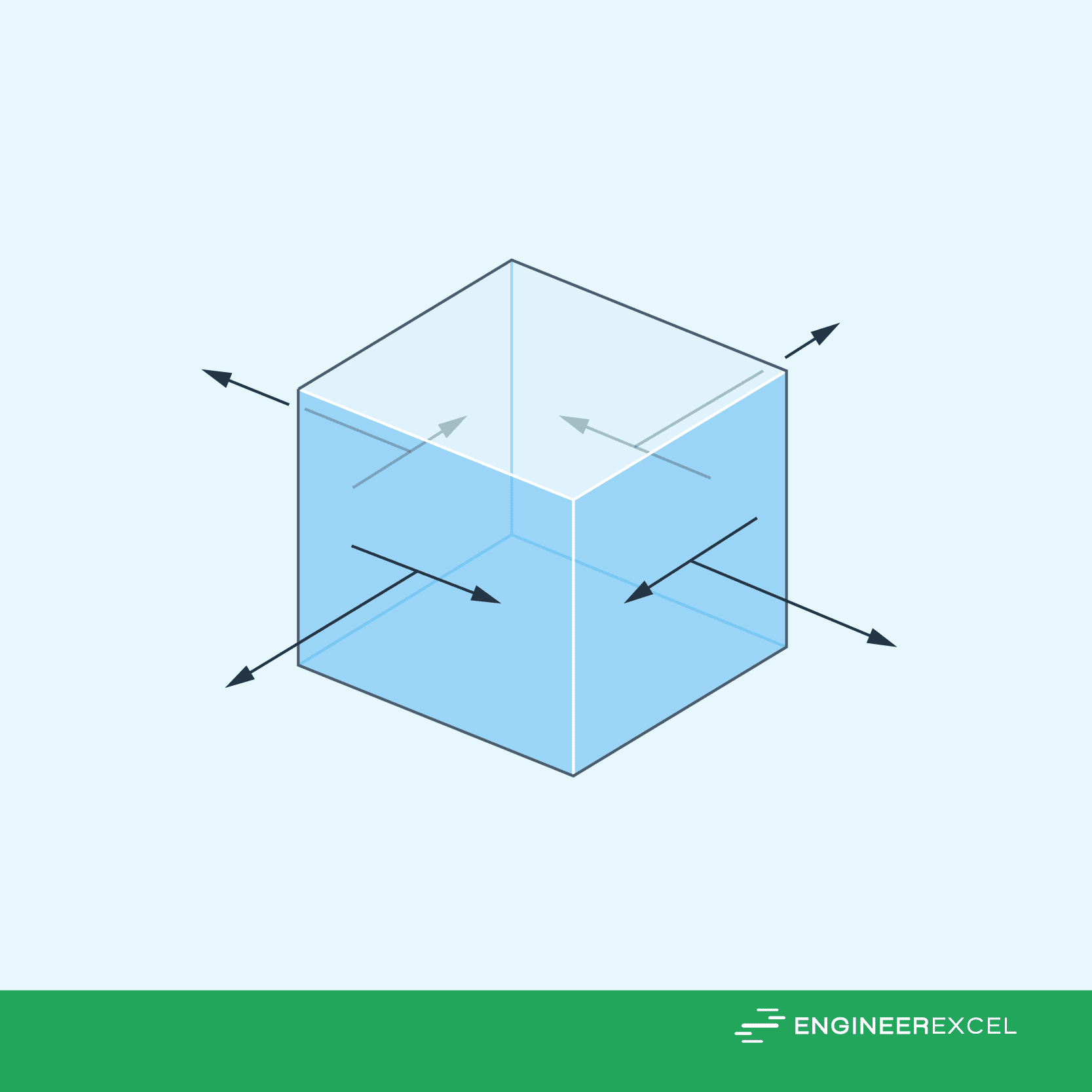
In general, the stress conditions at a point in a structure are determined by six distinct normal and shear stress components that affect the faces of a material element at that point. However, this state of stress is not commonly found in engineering applications.
Instead, engineers often simplify the loadings on a body to analyze the stress produced in a structural member or mechanical element in a single plane. In such cases, the material is considered to be experiencing plane stress.
Plane stress refers to the state of stress existing within a flat, two-dimensional element that is loaded in its plane. For example, if a body’s surface is not under any load, the normal and shear stress components on the face of an element lying on that surface will be zero. This means that the stress components on the opposite face will also be zero, resulting in the material at that point being subjected to plane stress.

Elevate Your Engineering With Excel
Advance in Excel with engineering-focused training that equips you with the skills to streamline projects and accelerate your career.
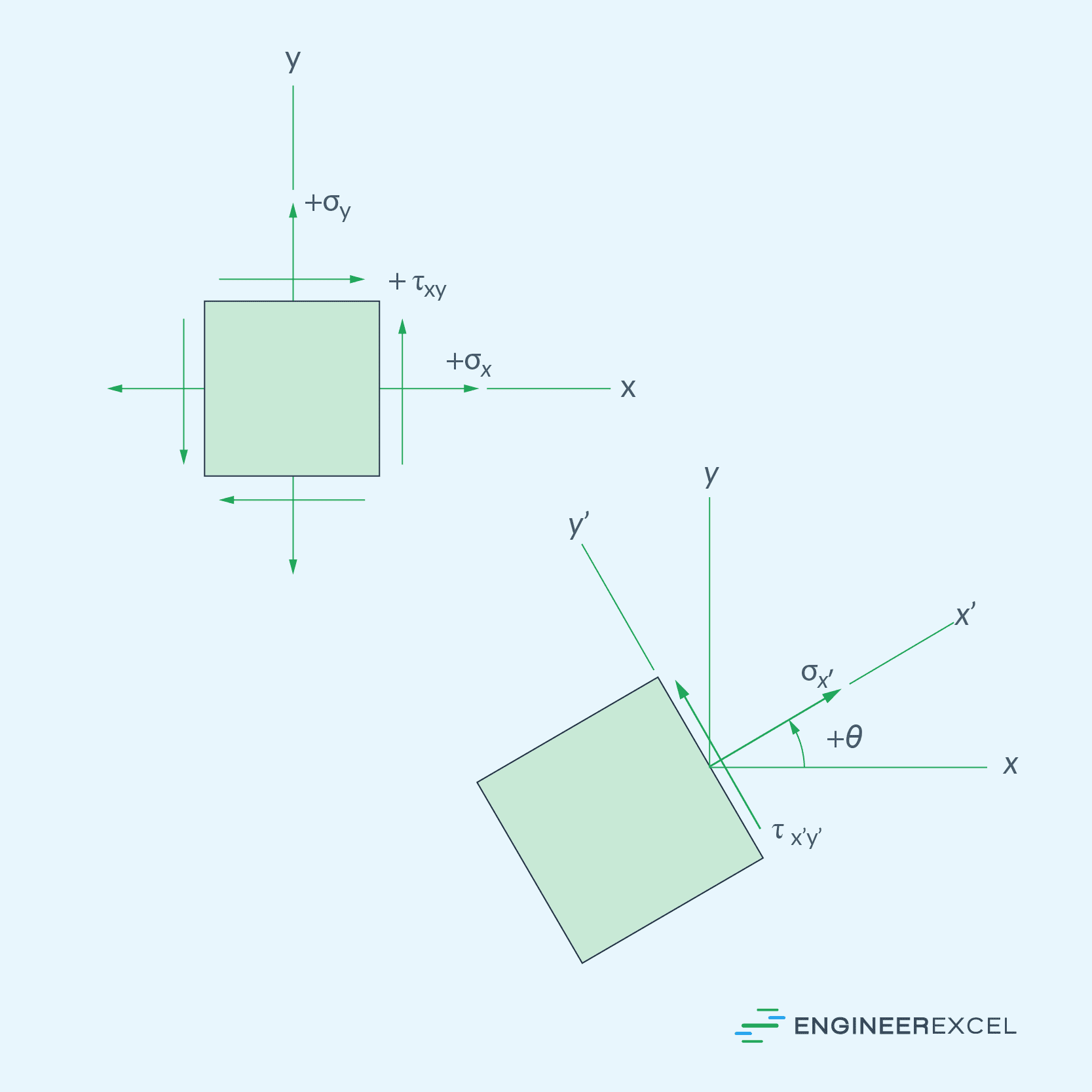
In plane stress analysis, the general state of stress is characterized by two normal-stress components and one shear-stress component that apply to four faces of the element. This is shown in the diagram below.
The stress components that act on an element are dependent on its orientation. Therefore, if the orientation changes, the stress components will also change.
This transformation of stress components from one orientation to another is known as stress transformation. It can be likened to determining two force components that act on a specific axis orientation to produce a resultant force and then finding the force components that act on a different axis orientation to produce the same resultant force.
Plane Stress Transformation
The transformation of plane stress can be achieved by using either stress-transformation equations or the graphical method known as Mohr’s Circle.
General Equations of Plane Stress Transformation
Suppose the plane stresses, σx, σy, and τxy, acting on xy-plane will be transformed to equivalent set of stresses, σx’, σy’, and τx’y’, acting on x’y’-plane, inclined at an angle θ.
The transformation equations for plane stress are given by:
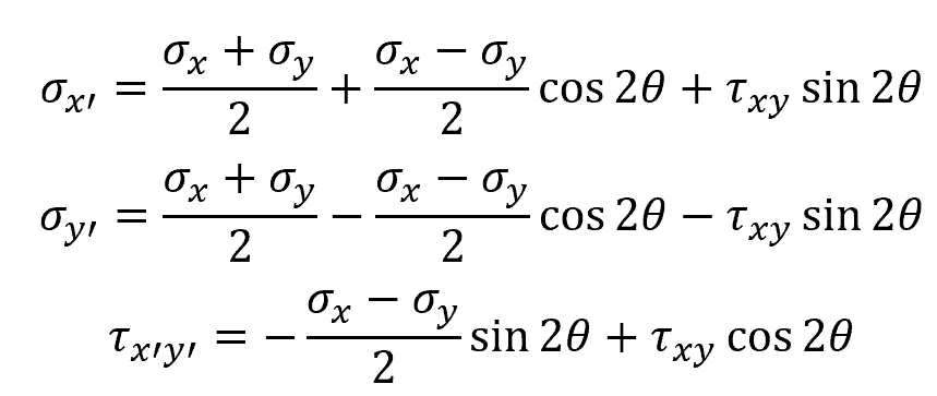
Where:
- σx = normal stress along x axis [Pa]
- σy = normal stress along y axis [Pa]
- τxy = shear stress acting on four faces [Pa]
- θ = angle between the original x-axis and the inclined x’-axis [rad]
- σx’ = transformed normal stress along x’ axis [Pa]
- σy’ = transformed normal stress along y’ axis [Pa]
- τx’y’ = transformed shear stress acting on four faces [Pa]
Note that the angle θ is measured from the +x axis to the +x’ axis. The angle will be positive provided it follows the curl of the right-hand rule.
Mohr’s Circle
Mohr’s Circle is a graphical representation of the state of stress at a point, which effectively simplifies the process of stress transformation and provides a clear visualization of the relationship between the normal and shear stresses for different orientations. It is constructed by establishing coordinate axes, σ positive to the right and τ positive downward, and then plotting a circle having a radius R and center located on the σ axis at a distance σavg from the origin. This is shown in the diagram below.
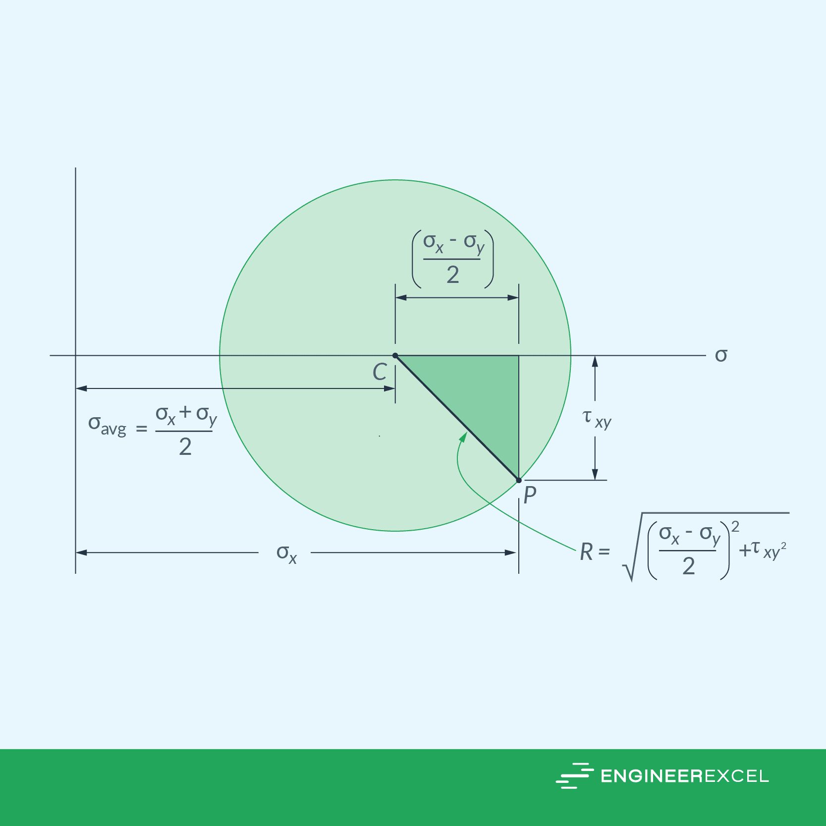
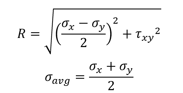
The radius and center location of the Mohr’s circle can be calculated using the following formula:
Each point on the Mohr’s circle represents the two stress components σx’ and τx’y’ acting on the orientation defined by x’ axis, inclined at an angle θ from the x axis. Note that a rotation θ of the axis on the element will correspond to a rotation 2θ on the Mohr’s circle in the same direction.
Mohr’s circle is a useful tool that can be utilized to identify different stress parameters. Once constructed, it can be used to determine the principal stresses, the highest in-plane shear stress, the average normal stress, and even the stress on any arbitrary plane.