
Strain transformation refers to the process of converting strain measurements from one coordinate system to another. This is often to simplify analysis or align with a preferred reference axis. In this article, we will explore the mechanics, sign convention, and equations of strain transformation.
Strain Transformation Explained
Strain is a measure of deformation experienced by a body due to applied stresses, temperature changes, or other external factors. There are two types of strain: normal strain and shear strain.
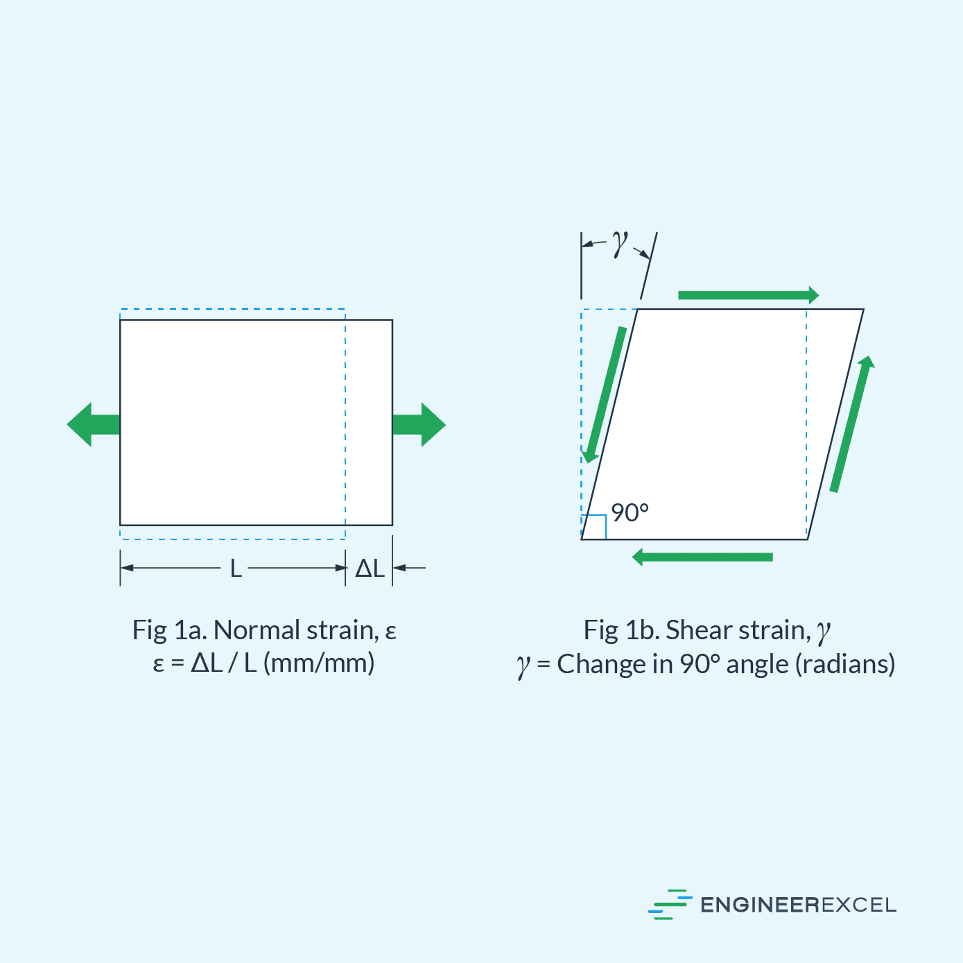
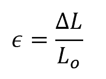
Normal strain represents the elongation or compression of the materials along the axis and is calculated using the equation:

Elevate Your Engineering With Excel
Advance in Excel with engineering-focused training that equips you with the skills to streamline projects and accelerate your career.
Where:
- ϵ = normal strain [unitless]
- ΔL = change in length of the material [m]
- Lo = original length of the material [m]
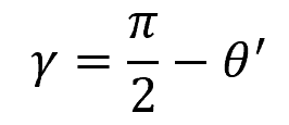
Shear strain, on the other hand, occurs in a material due to applied forces that cause the angle between the sides of the element to change. It is given by the equation:
Where:
- γ = shear strain [rad]
- θ’ = angle between the sides after deformation [rad]
In a three-dimensional body, a point can generally be represented by a combination of three components of normal strain (εx, εy, εz) and three components of shear strain (γxy, γyz, γxz). These components tend to deform each face of an element of the material. However, the normal and shear strain components at a point will vary according to the orientation of the element.
This variability implies that the strain measured in a specific direction may not be the same for a different direction. Therefore, it is important to determine how to transform strain from one orientation to another.
In this article, we will focus on transforming plane strain, a case where only two dimensions are assumed. This implies that the plane strain is subjected to only two components of normal strain (εx and εy) and one component of shear strain (γxy).
Sign Convention for Strain Transformation
Before proceeding with strain transformation equations, it is essential to understand the sign convention for strains in the context of stress and strain analysis. This convention allows for consistency when performing calculations and interpreting the results.

Normal strains are considered positive when they result in elongation along their respective axes. On the contrary, normal strains that cause compression along the axes are regarded as negative. For instance, if a material experiences an elongation in the x-direction, the normal strain (εx) would be positive, while compression in this direction would result in a negative εx.
For shear strains, the sign convention follows a set rule based on the change in the interior angle. If the interior angle becomes smaller than 90°, the shear strain is regarded as positive. Conversely, if the interior angle increases beyond 90°, the shear strain is considered negative.
Suppose an element is subjected to two components of normal strain (εx and εy) and one component of shear strain (γxy), measured relative to the x and y axes, as shown in the diagram below.
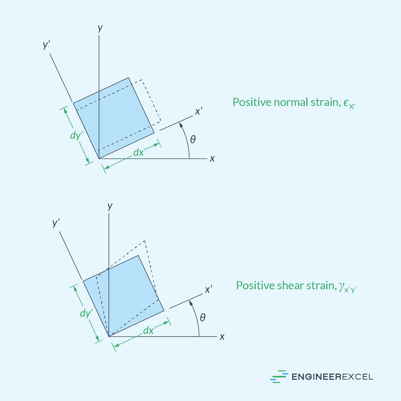
The goal of strain transformation is to determine the value of the transformed normal and shear strains (εx’, εy’, γx’y’), measured relative to the x’ and y’ axes, which are rotated at an angle θ from the original axes. In this case, θ is positive if it follows the curl of the right-hand fingers, that is, counterclockwise.
Strain Transformation Equations
Transforming strain from one orientation to another can be achieved using strain transformation equations. Considering the diagram above, the transformed normal strains along the x’ and y’ axes can be calculated using the following equations:
Where:
- ϵx’ = transformed normal strain along x’ axis [unitless]
- ϵy’ = transformed normal strain along y’ axis [unitless]
- ϵx = original normal strain along x axis [unitless]
- ϵy = original normal strain along y axis [unitless]
- θ = angle between the original x-axis and the transformed x’-axis [rad]
Similarly, the shear strain on the new coordinate axes (x’, y’) can be calculated using the following equation:
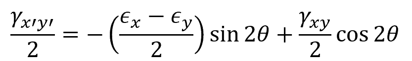
Where:
- γxy = original shear strain [rad]
- γx’y’ = transformed shear strain [rad]
Using these equations, we can find the normal and shear strain components in the transformed coordinate system, allowing us to study the strain transformation in materials subjected to different orientations. The understanding of strain transformation is essential for predicting material behavior under various loading and boundary conditions.