
Maximum shear stress theory is a framework for studying how ductile materials might fail due to stress. It is an important criterion to follow when designing safe parts. The theory is concerned with finding the maximum sheer stress value that will ultimately cause a material to deform.
What is The Maximum Shear Stress Theory of Failure?
As stated above, the maximum shear stress theory defines how a ductile material will fail when exposed to the maximum level of stress to cause plastic deformation. When we say plastic deformation, it means permanent. The material will not return to the shape or structure it was before it experienced this stress level.
This theory deals with its namesake: shear stresses. A force that causes stress and/or deformation along a plane parallel to the applied force is known as a shear stress. Common examples of shear stresses include the bottom of a shoe dragging on pavement as you walk, or a knife slicing through bread as you cut back and forth. They may also come from moment forces.
The key to this theory is that materials will only deform, will only break, under an element’s maximum shear stress applied (not referring to things like wear over time). Where that deformation (otherwise known as “yielding”) takes place also matters. The theory assumes that plastic yielding will occur along the plane of maximum shear stress.
Maximum shear stress theory states that yielding will occur when a particular point undergoes a maximum shear stress that is equal to half of the uniaxial yield strength. A uniaxial (“one-axis”) stress is a force acting in one direction, along its primary axis. A biaxial stress acts along two axes, like in the example of a column supporting a roof that is slightly bent off to one side, or a plank bending on its x and y axis.

Elevate Your Engineering With Excel
Advance in Excel with engineering-focused training that equips you with the skills to streamline projects and accelerate your career.
Who Hypothesized the Maximum Shear Stress Theory?
The maximum shear stress theory was first developed by the French mechanical engineer Henri Tresca in the late 1800s (it is sometimes referred to as the Tresca theory of failure). Tresca is known as the father of the field of plasticity, the study of irreversible material deformations. He developed one of the two main failure criteria for ductile materials, with Richard von Mises developing the other.
The Formula for Maximum Shear Stress Theory
We need to define a few things before giving the failure formula of the theory. First, let’s define what are known as the principal stresses.
Principal stresses are the stresses that occur along the axes of a material, specifically the “principal” axes (meaning the x, y, and z axes). The maximum allowable shear stress depends on the principal stresses in that it must not exceed the shear stress from uniaxial loading.
The formula for variable uniaxial shear stress failure is as follows:


For triaxial loading it is:

Or put in other terms:


And we can further simplify to:


where:
- τ = shear stress (N/m2 or Pa)
- σyield or σy = yield stress (N/m2 or Pa)
- σ1, 2, 3 or σx,y,z = principal stresses along x, y, and z-axis (N/m2)
If the structure undergoes biaxial loading, then one of the principal stresses will equal zero and the stress calculations will look like so (let σ3 = 0 here):


Here is how to calculate the principal stresses for biaxial loading, σ1, 2:
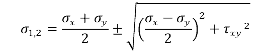
Solving for each:

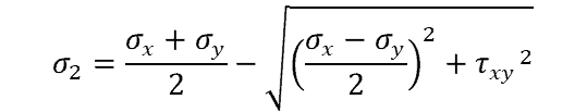
Knowing that σ1 – σ2 = σyield we can substitute terms in and solve for yield stress, leaving us with:

That right there is a lot of equations, but don’t fret. They’re largely just substitutions and different ways of solving for the same thing, depending on what variables are known.
Materials Used for Maximum Shear Stress Theory
Materials used in this stress testing must be considered ductile for it to apply. Ductile means that the material can be drawn out into thin wires without breaking and is susceptible to plastic deformation under tensile stress. Examples of ductile materials include metals like copper, steel, and aluminum.
Contrary to ductile materials are brittle ones. Materials that are brittle will break under tensile stress with no plastic deformation before sudden failure. That doesn’t necessarily mean the material is weak, as materials like concrete and cast iron, along with glass, fall under the brittle category. They may be hard, but not necessarily weak.
The same stress tests and theories for failure do not apply for both types of materials. Indeed, for brittle materials the maximum normal stress theory is used to test and study failure stresses.
Where Does the Maximum Shear Stress Occur?
Maximum shear stress is the most amount of concentrated stress in one small area. However, that is only where the maximum shear stress will be. If a beam is exposed to a shear stress, the amount of shear stress will rise then fall along the beam, usually in a manner that can be plotted.
For a cross section of rectangular beam, the amount of shear stress along the height of the cross section can be plotted as a parabolic curve. The shear stress will therefore be equal to zero at the top and bottom of the beam, and at its maximum in the middle, along what is known as the “neutral axis”. The neutral axis is not a set location, but rather where the normal stress and strain are equal to zero, and the shear stress is at its highest.
For a rectangular beam, this will often be in the middle of the beam. But if the beam is not rectangular or turned at an angle with respect to the load, the location of the neutral axis will shift. If the load is extremely large, for example, the neutral axis and location of maximum shear stress will shift upward.
Why Shear Stress is Highest at the Neutral Axis
Shear stress will be highest under a bending load at the neutral axis in a rectangular beam. As for why, it could make sense to think of the beam as a bunch of thin planks all stacked on top of one another. If they were all subjected to a load, they would shift, slip away from one another. Well, if each plank were to deflect a little from the one above it, then then the plank in the middle axis (along the beam’s height) would be deflected the most.
Why the middle and not the bottom? Well, the beam is better thought of as being split in half along the neutral axis, and so the shear stress increases as you come from the top and the bottom, reaching its maximum at the neutral axis.
It is worth noting that shear stress is at its highest along the neutral axis for squares and rectangular beams, but not other shapes such a triangular cross-section.
Is Tresca or Von Mises Failure Theory More Accurate?
The von Mises failure criterion is sometimes referred to as the maximum distortion criterion of failure. It is another way to study and design against failure in ductile materials. The main crux of this failure theory is that a material will yield (ie fail) when any point within the structure has distortion energy per unit volume that equals the yield stress done by a simple tensile test.
Distortion energy per volume is also known as von Mises stress. It’s another way of looking at ductile material failure. While the two theories are studying the same result, they get there via different methods.
So which theory is more accurate, and which should be used where? Both theories rely on figuring out the principal stresses on a material. And both also rely on finding the allowable yield stress.
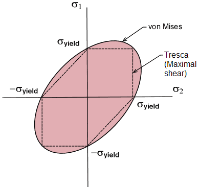
The maximum shear stress theory is more conservative than the von Mises theory and predicts a more narrow elastic region where a material will maintain shape. From a design standpoint, this may result in a safer and more forgiving design. However, relying on the maximum shear stress theory may result in an engineer designing unnecessarily costly part.
The main difference between the two methods is that the von Mises looks at the maximum allowable distortion energy, instead of the maximum allowable shear stress. While Tresca’s theory was originally thought to be more fundamental, at one point von Mises’ became more practical as it was simpler, and now with modern computing capabilities both can be used as necessary.