
A strain gauge is a device used to measure deformation in materials, based on the principle that a wire’s resistance increases with strain. Using this device, engineers can assess the mechanical behavior of materials and ensure the reliability and durability of components under different loads and conditions.

In this article, we will explore how strain gauges work, including their construction and the calculations involved in strain measurement.
Understanding How a Strain Gauge Works
Understanding the stress within a material is important for engineers as it helps them assess its mechanical behavior and guarantee the reliability and durability of components under different loads and conditions. However, there is no direct method for measuring stress.
As a result, surface strain is often measured to infer internal stress. There are several devices that can be used to measure strain, but in this article, our focus will be on electrical resistance strain gauge.

Elevate Your Engineering With Excel
Advance in Excel with engineering-focused training that equips you with the skills to streamline projects and accelerate your career.
An electrical resistance strain gauge, or simply strain gauge, is a device used to measure deformation based on the principle that a wire’s resistance increases with strain. This principle can be represented using the following equation:
Where:
- R = resistance of the wire [Ω]
- ρ = resistivity of the wire material [Ω-m]
- L = length of the wire [m]
- A = cross-sectional area of the wire [m2]
Usually made of thin wire or foil grid, the strain gauge is attached to the surface of the material under study. When the material deforms due to stress, the strain gauge also deforms, causing a shift in its electrical resistance.
By gauging this altered resistance, the strain gauge can indirectly measure the strain, facilitating the computation of stress and offering valuable data for material testing, structural analysis, and industrial applications.
It’s important to understand that strain gauges are available in different configurations and sensitivity levels. Additionally, various factors, including temperature, material properties, and installation procedures, can impact their performance.
Construction of a Strain Gauge
Most strain gauges are of foil construction made through printed-circuit process. It typically comprises three main components: the conductive grid, the backing material, and the adhesive. These are illustrated in the diagram below.

The conductive grid is usually made from a thin metal foil, such as constantan or advanced alloys. This grid pattern is etched onto the metal foil to create a continuous conductive path.
The resistance of this path changes as the grid is subjected to strain, which is the property utilized for the measurements. The size, shape, and design of the grid affect the gauge’s sensitivity, temperature characteristics, and fatigue life.
The backing material acts as a support for the delicate conductive grid. It is typically made from a flexible plastic material like polyimide or polyester that can adhere to irregular surfaces and follow the strain of the test specimen without significantly affecting the measurements. The backing should also be chemically stable, have low creep, and good insulating properties.
The adhesive is used to attach the strain gauge to the test specimen. It must provide a strong and stable bonding between the gauge and the structure, ensuring that the strain experienced by the test specimen is accurately transferred to the strain gauge. Various adhesive materials are available, such as epoxy or cyanoacrylate, which provide different bonding strengths, temperature resistances, and curing times.
Strain Gauge Calculations
When attached to the surface of the object, the strain gauge undergoes the same deformation as the object being studied, leading to a shift in its electrical resistance. The change in resistance in the strain gauge is directly related to the axial strain, as shown in the following formula:
Where:
- δR = resistance change [Ω]
- S = strain gauge factor [unitless]
- ϵa = axial strain [unitless]
S is typically around 2.0 for commercially available strain gauges.
The resistance change due to the applied strain can be measured using the Wheatstone bridge circuit, as shown in the schematic diagram below.
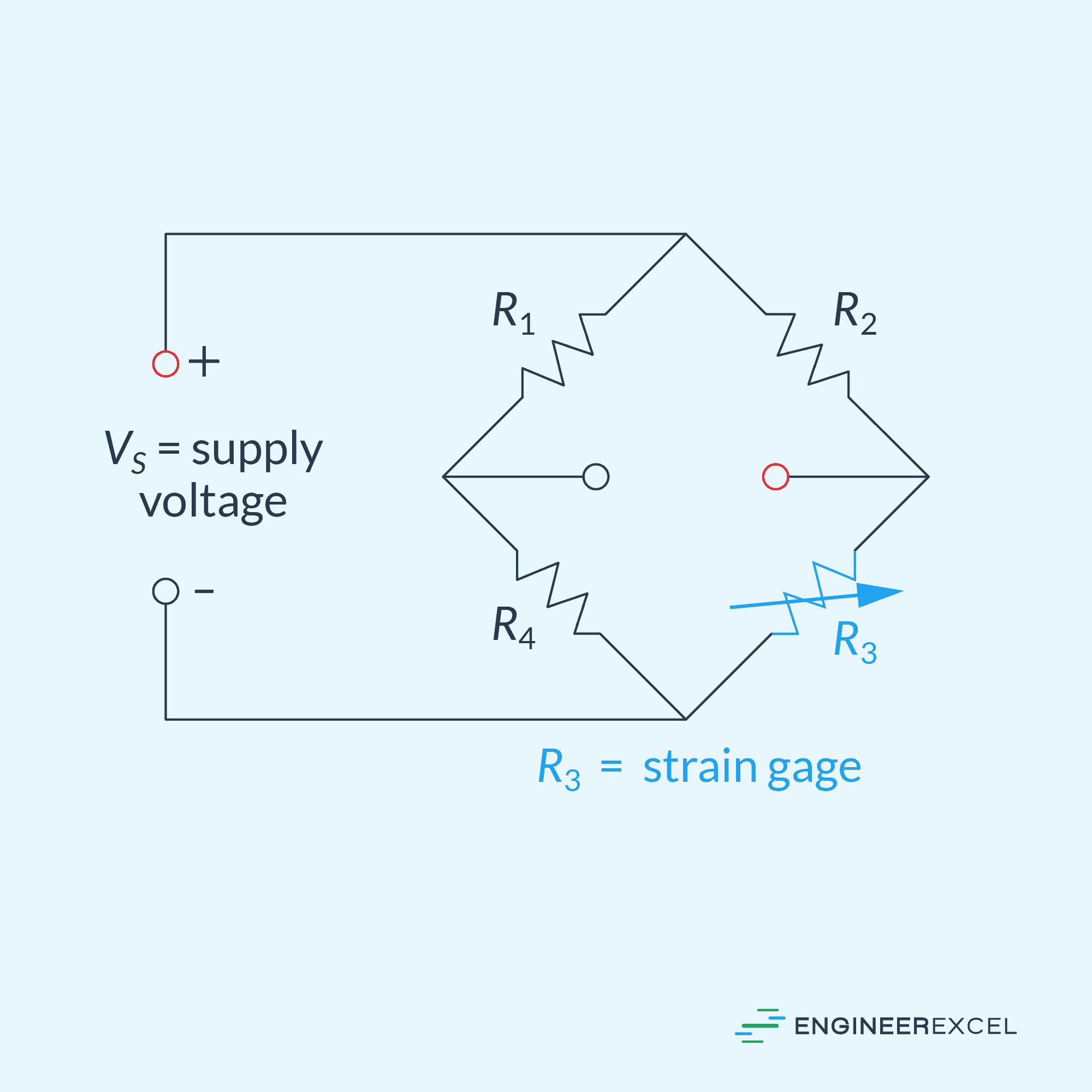
A DC voltage is applied across the bridge, which consists of four resistors arranged in two parallel legs, each with two resistors in series. The output voltage is measured across the midpoints of the legs. To measure strain, one of the resistors is substituted with the strain gauge.
Under normal conditions, the Wheatstone bridge is initially balanced, with all resistors, including the strain gauge, having the same resistance values. If strain is applied to the strain gauge, causing its resistance to change by a small amount δR, the bridge becomes unbalanced, and the resulting output voltage can be calculated using the following formula:
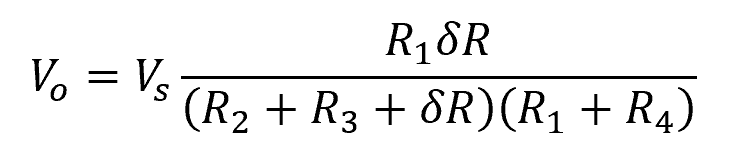
Where:
- Vo = output voltage [V]
- Vs = supply voltage [V]
- R1, R2, R3, R4 = initial resistance of each resistor [Ω]
Equating the above two equations, the formula for the axial strain becomes:
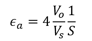
This formula can be used to calculate for the axial strain using the output voltage of the circuit, instead of the change in resistance of the strain gauge.