
Cylindrical or spherical vessels are frequently utilized in industries as boilers or tanks for storing pressurized fluids. Because of the pressure inside and outside of the vessel, the vessel material experiences loading from all directions.
Hoop Stress Derivation
When a vessel is subjected to internal and external pressure, the resulting normal stresses are functions of the vessel’s radius, shape, and the magnitude of the applied pressure. In general, three types of stresses occur to pressure vessels: radial, axial, and hoop.
Radial stress acts radially inward or outward from the center of the vessel, axial stress acts parallel to the longitudinal axis along the surface of the vessel, while hoop stress acts tangentially to the circumference of the vessel.
Hoop stress occurs in both directions and is similar to the way a hoop or a ring is stressed when it is stretched or compressed. In this article, the focus is on the derivation of the formula for hoop stress for both thin-walled and thick-walled pressure vessels.

Elevate Your Engineering With Excel
Advance in Excel with engineering-focused training that equips you with the skills to streamline projects and accelerate your career.
Hoop Stress for Thin-Walled Vessels
In most applications, the design calculations for pressure vessels are often simplified by assuming that they have a thin wall. A vessel is considered to have a thin wall if the ratio between its inner radius and wall thickness is at least 10.
At a ratio of exactly 10, a thin-wall analysis predicts a stress that is about 4% less than the actual maximum stress. The analysis gets more accurate as this ratio increases.
Despite being subjected to loading from all directions, considering a thin wall simplifies the analysis by assuming that the stress distribution through its thickness remains relatively constant. In addition, thin-wall analysis assumes that the plane sections remain plane, and that the vessel material is linearly elastic, isotropic, and homogeneous.
Normally, when performing thin-wall stress analysis, the radial stress is also ignored— that is, only the axial and hoop stresses are considered. Assuming zero external gauge pressure, the radial stress reaches its peak value at the inner wall of the vessel, which is equivalent to the pressure p. This gradually diminishes across the wall until it reaches zero at the outer surface.
However, because the wall of the vessel is much thinner than its radius, the maximum radial stress is known to be 5 and 10 times lower than the axial and hoop stress, respectively. Hence, it is deemed insignificant in most cases.
The formula for calculating the hoop stress depends on whether the thin-walled vessel is cylindrical or spherical, as shown in the succeeding sections.
Hoop Stress Formula for Thin-Walled Cylindrical Tank
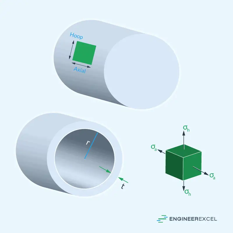
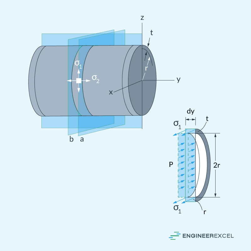
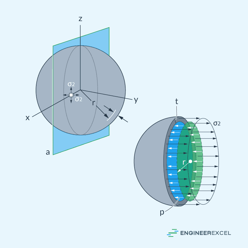
To derive the formula for the hoop stress of a pressurized thin-walled cylindrical tank, consider the diagram below with wall thickness t, inner radius r, and gauge pressure p. Because of the pressure, each small element of the cylindrical vessel experiences two major stress vectors: σa, which is the axial stress, and σh, which is the hoop stress.
The diagram below shows the resulting internal reactions along the x axis which are due to hoop stress acting on the incremental area equal to 2t(dy), and the gauge pressure acting on a projected area equal to 2r(dy).
Equating the sum of forces along the x axis to zero:
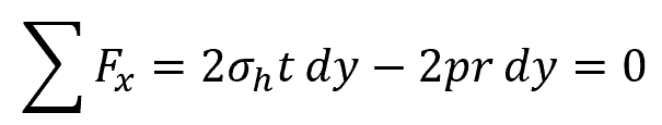
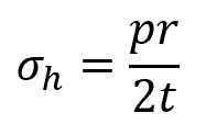
The equation above can be rearranged to obtain the formula for hoop stress:
Where:
- σh = hoop stress [N/m2 or psi]
- p = internal gauge pressure [N/m2 or psi]
- r = inner radius of the cylindrical vessel [m or in]
- t = thickness of the cylindrical vessel [m or in]
Note that the hoop stress is assumed to be constant throughout the wall of the cylinder, and that the ratio r/t should be greater than or equal to 10.
Hoop Stress Formula for Thin-Walled Spherical Tank
To derive the formula for the hoop stress of a pressurized thin-walled spherical tank, consider the diagram below with wall thickness t, inner radius r, and gauge pressure p. Since the tank has a symmetrical shape in all directions, the pressure results in an equal value for the axial and hoop stress.
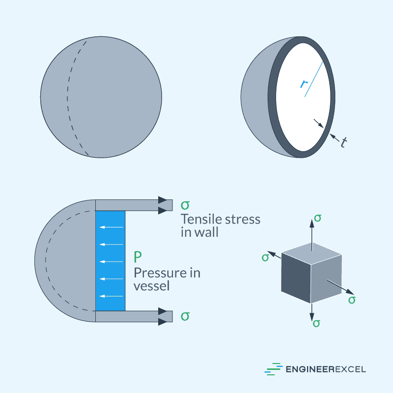
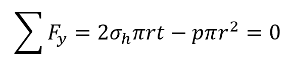
The diagram below shows the resulting internal reactions along the y axis which are due to the hoop stress acting on the area approximately equal to 2πrt, and the gauge pressure acting on a projected area equal to πr2.
Equating the sum of forces along the y axis to zero:
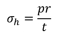
The equation above can be rearranged to obtain the formula for hoop stress:
Notice that the hoop stress for a spherical vessel is only half of the hoop stress of a similarly sized cylindrical vessel. This is the reason why some cylindrical tanks have spherical end caps— to reduce the stress in the tank.
Hoop Stress for Thick-Walled Vessels
The method for determining the hoop stress of thick-walled vessels uses the concept of elasticity and is always applicable regardless of the r/t ratio.
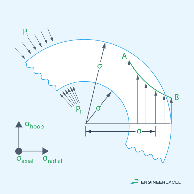
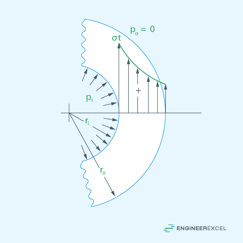
Consider a cylindrical thick-walled vessel with an inner radius ri, outer radius ro, internal pressure pi, and outer pressure po. The resulting hoop stress distribution is shown in the diagram below, with the highest hoop stress value occurring at the innermost part of the shell.
Now consider an element situated at radius r, which is defined by a radial increment dr and an angle increment dθ, as shown in the diagram below.
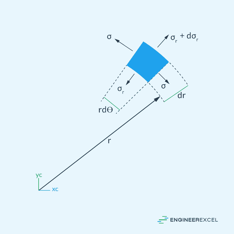
Assuming that the thickness of the element is one unit and that the shear stress on the element is zero, the equilibrium of the radial forces leads to the following equation:

Using Hooke’s Law and assuming that the boundary conditions for the inner and outer radial stresses are equal to pi and po, respectively, the hoop stress formula transforms to be:
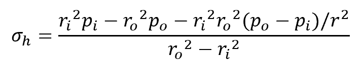
Where:
- ri = inner radius [m or in]
- ro = outer radius [m or in]
- pi = internal pressure [N/m2 or psi]
- po = external pressure [N/m2 or psi]
- r = radial variable [m or in]
Hoop Stress Applications
Structures that hold internal pressure, such as pipes, tanks, and bottles, are essential in many industries. However, their safe operation relies on adequate design.
Hoop stress is one of the critical factors that needs to be considered in engineering pressurized vessels. The circumferential stress that occurs in cylindrical or spherical objects under pressure can cause catastrophic consequences if not accurately calculated, particularly in high-pressure applications.
Therefore, hoop stress calculations are essential for ensuring safety and selecting the appropriate materials. If the hoop stress exceeds the material’s yield strength, deformation, leakage, or even rupture can occur. This calculation can also help optimize the cost of a component by minimizing its weight and cost while ensuring its safety and durability.
Finally, many engineering codes and standards require hoop stress calculations to be performed and documented for pressure vessel and piping designs. Compliance with these standards is necessary to ensure that the design meets the required safety and reliability standards.