
Principal strains refer to the maximum and minimum normal strains experienced by an object or material in a specific direction, representing the deformation or change in length along those axes. These strains are important in analyzing the extent of how materials respond to external forces and stresses.
In this article, we discuss the concept of principal strains, their calculation, and how they can be determined using Mohr’s Circle.
Understanding Principal Strains
Strain is a measure of deformation experienced by a material when it is subjected to external forces. Specifically, it is expressed as the ratio of the change in dimensions to the initial dimensions of the material.
The state of strain of a point in a material can generally be represented by three normal strain components and three shear strain components. Normal strain measures the deformation in the direction perpendicular to the applied force, while shear strain quantifies the distortion or angular change resulting from forces applied parallel to the material.

Elevate Your Engineering With Excel
Advance in Excel with engineering-focused training that equips you with the skills to streamline projects and accelerate your career.
The values of these components may vary depending on the orientation of the element. Hence, similar to stress, an element can be oriented at a point such that the normal strains are at their maximum and minimum values. When this occurs, the normal strains are referred to as principal strains.
At this point, there is no shear strain. That is, the element’s deformation is caused by the normal strains alone. For isotropic materials, the axes along which the principal strains occur will coincide with the axes that define the planes of principal stress.
When analyzing a structure, it is essential to determine the principal strains as these can provide vital information about the material’s deformation and possible failure. The principal strains indicate the maximum and minimum normal strains experienced by the material, and these values can be used to analyze the material’s stability and safety.
Calculating Principal Strains
The equations for calculating principal strains are derived from strain transformation equations.
Suppose a point in a material is subjected to two components of normal strain (εx and εy) and one component of shear strain (γxy), measured relative to the x and y axes, as shown in the diagram below.
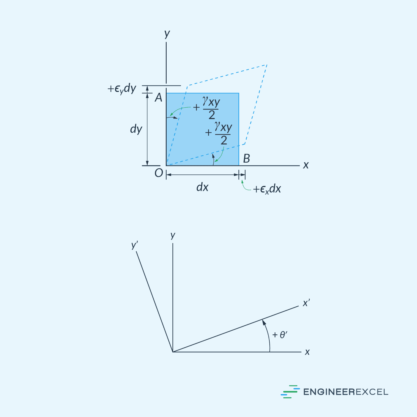
To determine the orientation of the x’-y’ plane at which the principal strains would occur, the following formula can be used:
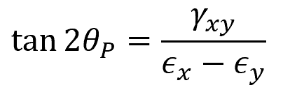
Where:
- θP = angle between the x and x’ axes [rad]
- γxy = original shear strain [rad]
- ϵx = original normal strain along x axis [unitless]
- ϵy = original normal strain along y axis [unitless]
Note that the sign convention for θP follows the right-hand rule. This means that θP is considered positive when the x’ axis is oriented in the counterclockwise direction from the x axis, and negative when it is oriented in the clockwise direction.
To obtain the values of the principal strains, the following equation can be used:
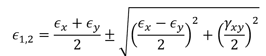
Where:
- ϵ1,2 = principal strains [unitless]
Note that the equation above has two solutions. These two solutions pertain to the two principal strains. The higher value ϵ1 is the maximum principal strain, while the lower value ϵ2 is the minimum principal strain.
Determining Principal Strains Using Mohr’s Circle
Similar to plane stress, it is possible to create a Mohr’s Circle for plane strain. This is a graphical representation used to analyze and visualize the states of strain at different orientations in a material under various loading conditions. It can also be used to determine the principal strains from a given state of strain.
The equation for the Mohr’s circle for plane strain is given as:
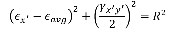
Where:
- ϵx’ = transformed normal strain along an arbitrary x’ axis [unitless]
- γx’y’ = transformed shear strain [rad]
- ϵavg = average normal strain [unitless]
- R = radius of the Mohr’s circle [unitless]
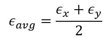
This circle has a center at:
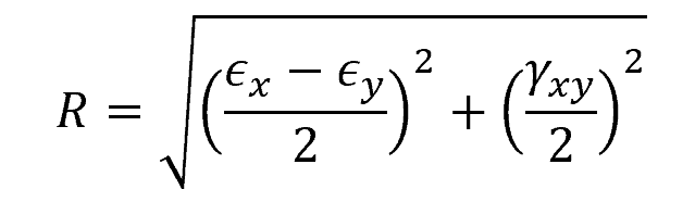
Moreover, the radius is equal to:
The resulting Mohr’s circle is shown below.
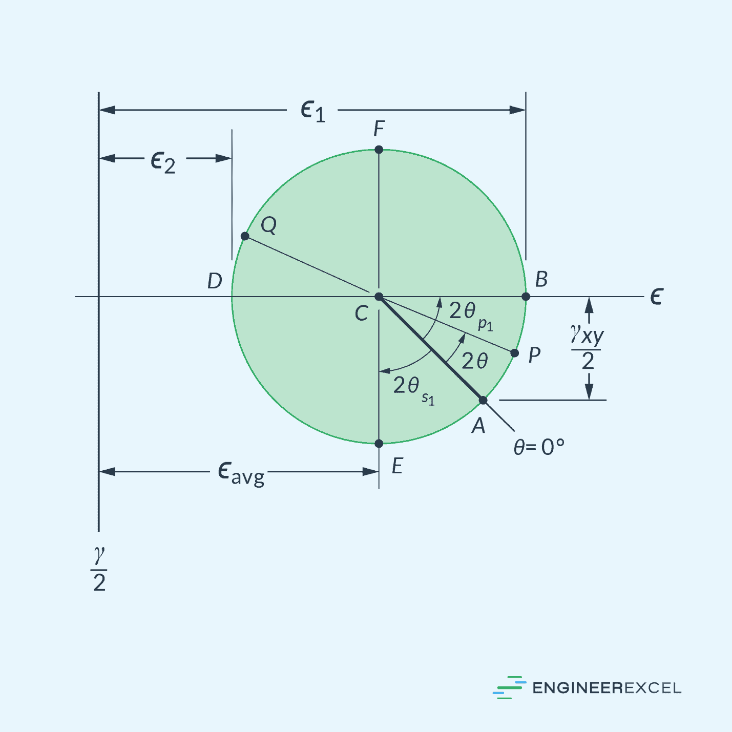
As shown in the diagram above, the principal strains ϵ1 and ϵ2 can be found at the intersections between the circle and the horizontal axis. At these points, the shear strain is equal to zero.