
Plane strain is a condition in solid mechanics where an object experiences deformation only in two dimensions, while the deformation in the third dimension is constrained or negligible. This simplification is often applied to analyze the behavior of structures subjected to loads that are predominantly in a specific plane.

In this article, we will discuss the concept of plane strain, the different strain measurement methods, and the differences between plane strain and plane stress.
Understanding Plane Strain
In a three-dimensional body, the state of strain at a point can be described by three normal strain components and three shear strain components. These components cause deformation in each face of the material element.
However, in certain cases, it’s practical to simplify the analysis by focusing only on strains in two dimensions. This is known as plane strain.

Elevate Your Engineering With Excel
Advance in Excel with engineering-focused training that equips you with the skills to streamline projects and accelerate your career.
This can be applied in situations where the strain value in one of the dimensions pales in comparison with the other dimensions. For instance, in a long metal billet, the length greatly exceeds the other dimensions, resulting in a small strain along the length compared to the cross-sectional strains. In this case, plane strain is an acceptable approximation.
In plane strain analysis, the strain state is expressed as (εx, εy, γxy), with normal strains (εx, εy) along the x- and y-axes and shear strain (γxy) in the xy-plane, as illustrated in the diagram below.
Remember that normal strain, denoted by ϵ, is a measure of the relative change in length of a material along a particular axis. Mathematically, it is defined as the ratio of the change in length to the original length of the material:
Where:
- ϵ = normal strain [unitless]
- ΔL = change in length of the material [m]
- Lo = original length of the material [m]
Normal strain indicates how much a material has stretched or compressed along a specific direction.
On the other hand, shear strain, denoted by γ, describes the change in shape of a material due to the application of shear stress. Mathematically, it is defined as the change in angle between two originally perpendicular sides in a material:
Where:
- γ = shear strain [rad]
- θ’ = angle between the sides after deformation [rad]
Shear strain quantifies the deformation that results from forces applied parallel to a surface, causing one layer of the material to slide relative to an adjacent layer.
In general, normal strains are positive if they cause elongation along the axis, and the shear strain is positive if the interior angle becomes smaller than 90°.
Measuring Plane Strain
Measuring plane strain is important for understanding the deformation and stress distribution in materials. There are direct and indirect methods employed to measure plane strain, each having its own advantages and limitations.
Direct strain measurement relies on electrical-type gauges such as resistive, capacitive, or inductive.
Resistive strain gauges involve the usage of metallic grids, which vary electrical resistance upon deformation. Capacitive strain gauges work through measuring changes in capacitance due to the deformation of a dielectric material. Finally, inductive strain gauges detect variations in inductance resulting from the deformation of a coil.
Indirect strain measurement techniques are optical. These include photoelasticity, the Moiré technique, and holographic interferometry.
Photoelasticity allows the visualization of stress distribution using birefringent materials. When subjected to stress, these materials exhibit refractive index changes proportional to strain. Analyzing the pattern of light transmitted through the stressed material helps to determine the strain distribution.
The Moiré technique employs the interaction of two sets of periodic fringes, one on the object and another on a reference grid, to create an interference pattern. This pattern provides information about the in-plane deformation.
Holographic interferometry relies on the interference of two laser beam paths: one reflecting off the object’s surface in two different states (deformed and undeformed) and the other serving as a reference. The interference pattern produced by these paths yields information about strain distribution on the object’s surface.
Plane Strain vs Plane Stress
Plane stress is defined by two normal stress components and one shear stress component lying in the same plane. In the same way, plane strain is defined by two normal strain components and one shear strain component lying in the same plane.
However, even they are both defined by three components lying in the same plane, it is important to note that plane stress does not necessarily cause plane strain or vice versa. This is because of the Poisson effect, which refers to the phenomenon in which a material undergoes lateral contraction when stretched longitudinally or expands laterally when compressed.
To visualize, consider the free-body diagram of an element subjected to plane stress, below.
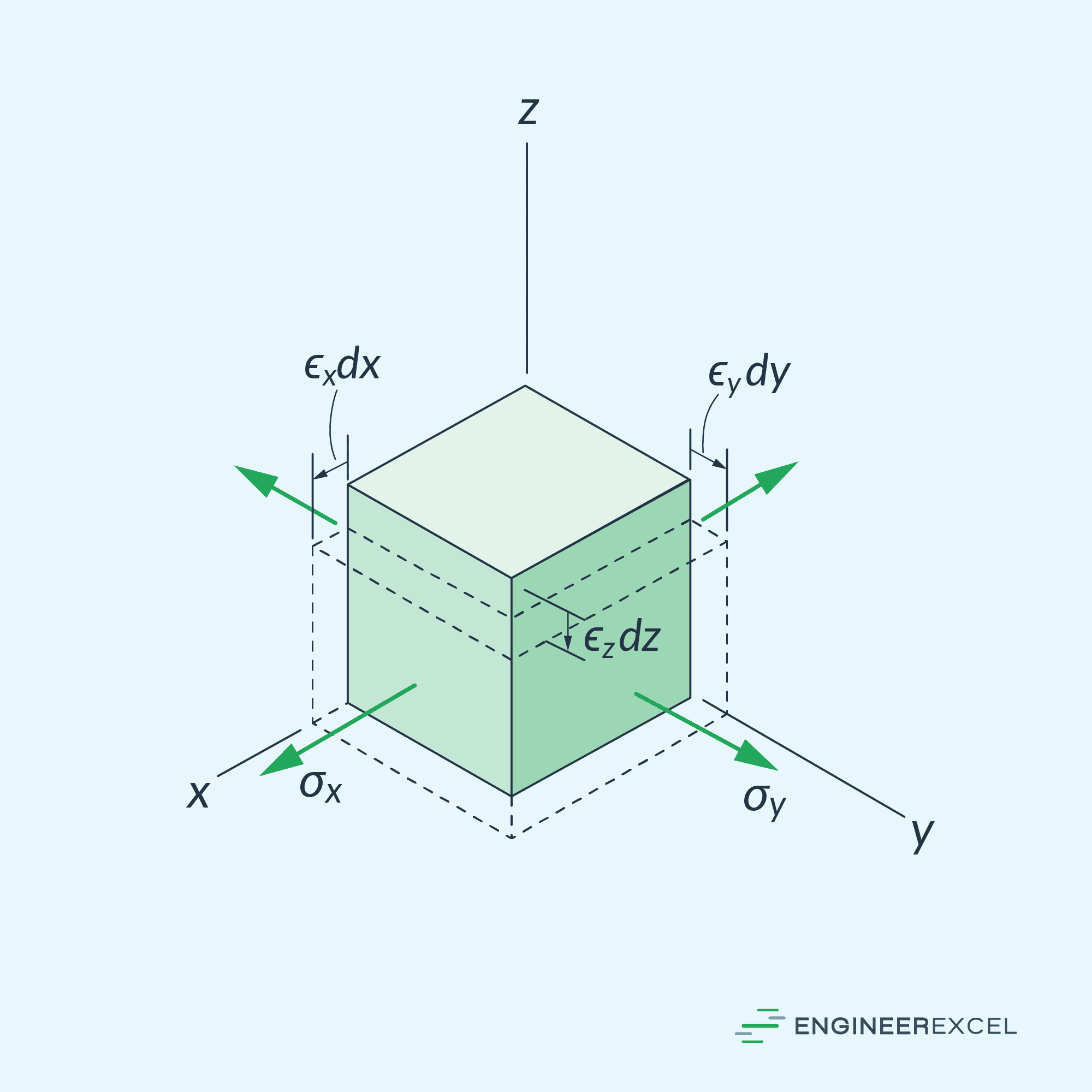
When an elastic element is subjected to plane stress σx and σy, not only are normal strains ϵx and ϵy produced, but there is also an associated normal strain ϵz produced as a result of the Poisson effect. Hence, the resulting state of strain is not a case of plane strain. Unless the Poisson ratio of a material is zero, the Poisson effect will not allow the simultaneous occurrence of plane strain and plane stress.