
A rosette strain gauge is a device used to measure the deformation or strain of an object in multiple directions. It consists of three or more individual gauges arranged at specific angles to measure normal strains along different axes, providing essential data for understanding complex stress conditions and predicting potential failure points.
In this article, we will discuss how strain rosettes work, their different configurations, and the calculations involved in determining the state of strain at a point using strain rosettes.
What is A Rosette Strain Gauge?
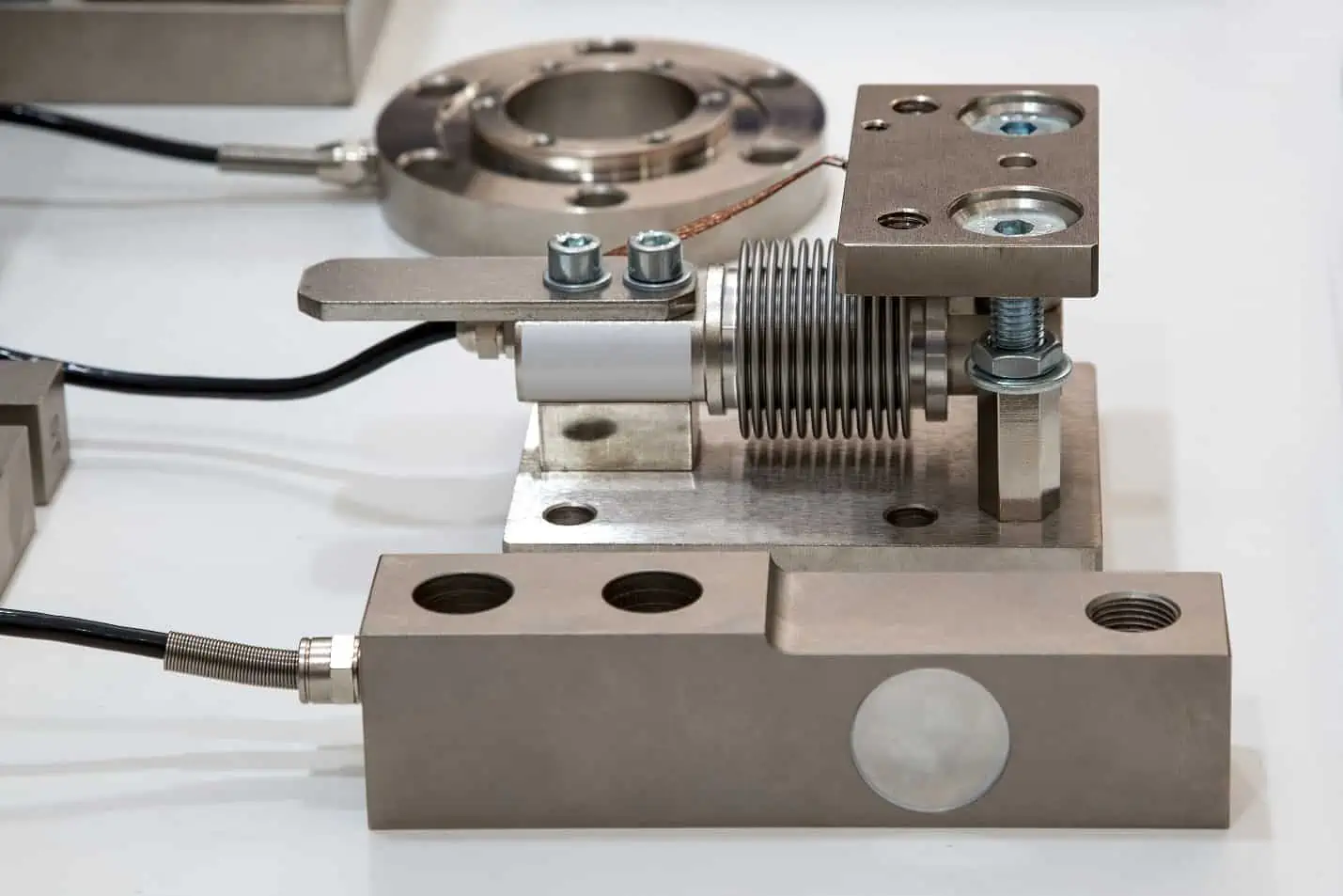
A strain gauge is a device used to measure the axial deformation or strain of an object. It usually comprises a thin wire or foil affixed to the surface of the object experiencing deformation.

Elevate Your Engineering With Excel
Advance in Excel with engineering-focused training that equips you with the skills to streamline projects and accelerate your career.
When the object deforms, the strain gauge also deforms, leading to a change in its electrical resistance. This change can be measured and linked to the amount of strain experienced by the object.
While a strain gauge can effectively measure strain in one direction, it only provides information about the deformation along a single axis. However, it is often important to understand strain in multiple directions to fully characterize deformation.
For instance, in a general biaxial stress state where the principal directions are unknown, three independent strain measurements in different directions are needed to determine the principal strains and stresses. And even if the principal directions are known, it still requires two independent strain measurements to calculate for the principal strains and stresses. This is where rosette strain gauges come in.
A rosette strain gauge consists of three or more individual gauges arranged at specific angles to measure normal strains along different axes. Once the normal strains on the three gauges are measured, the data can then be transformed to specify the state of strain at the point.
They are particularly useful for determining the principal strains and directions, as well as the maximum shear strains occurring within a material. These measurements are essential for understanding the material’s behavior under complex stress conditions and for predicting potential failure points.
Rosette Strain Gauge Configurations
Rosette strain gauges can be arranged in different configurations. However, the most common configurations are the 45-degree and 60-degree strain rosettes, shown in the diagram below.
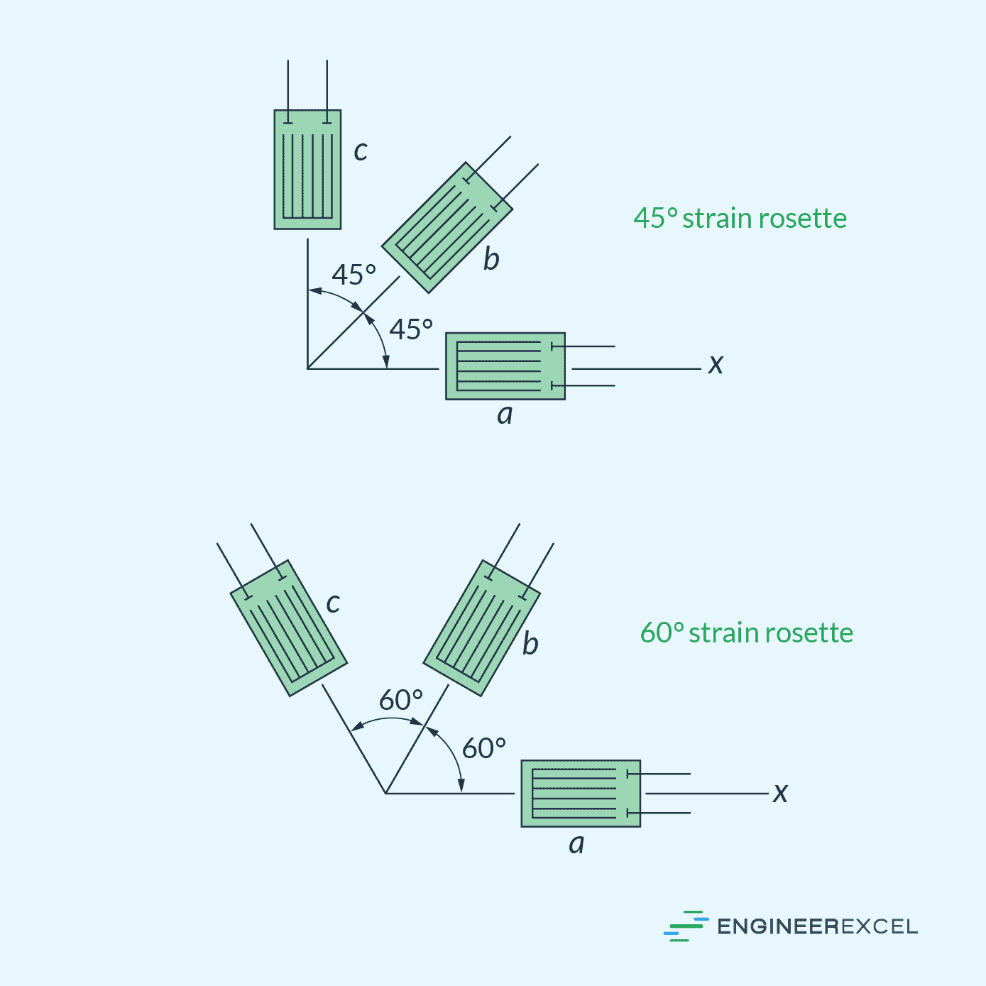
When installing a rosette strain gauge, it is essential to ensure accurate alignment of strain gauges. It can be made by gluing three strain gages to the surface or, in some cases, a template or mount can be employed to ensure proper alignment.
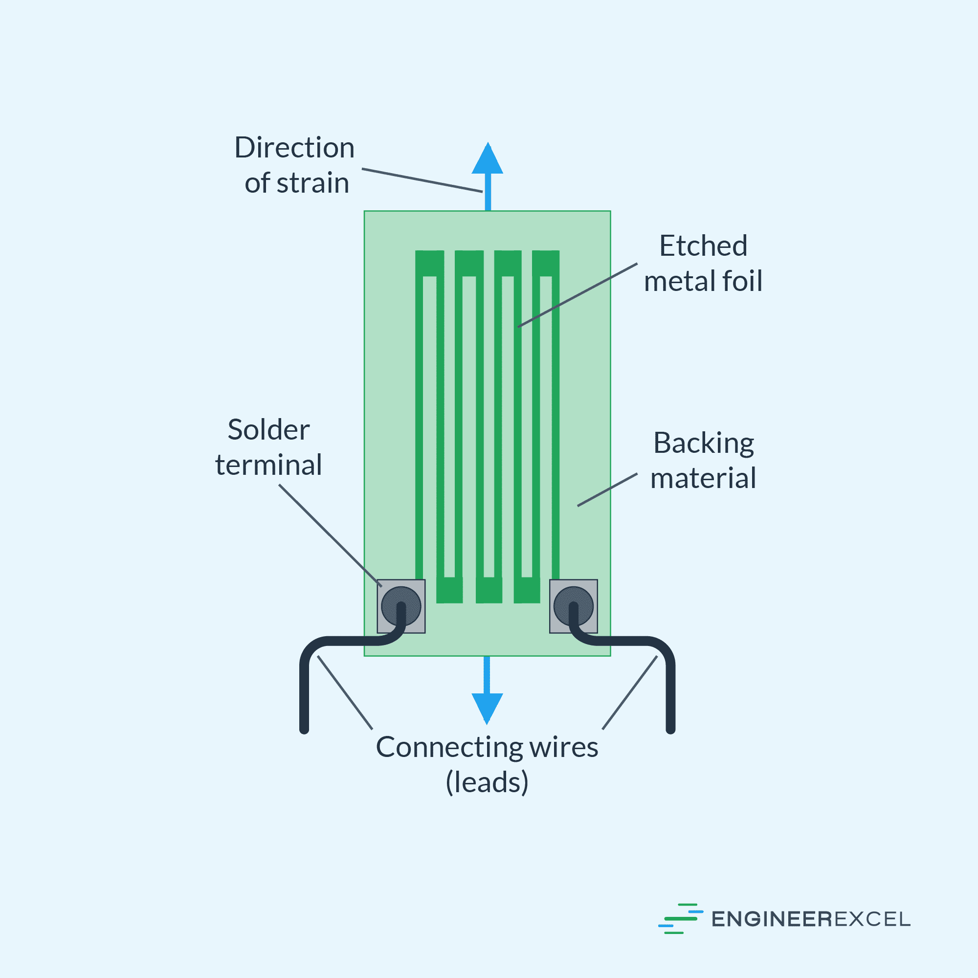
Since strain gauges themselves are commonly constructed from metal foil etched onto a plastic substrate, another option is to directly etch all the strain gauges on a single substrate to form a ready-made strain gauge rosette.
Rosette Strain Gauge Calculations
As previously mentioned, determining the axial strains in three different directions allows us to define the state of strain at a point and calculate the magnitude and direction of the principal strains and the maximum shear strain.
To illustrate this process, consider the diagram below, which depicts a general configuration of a rosette strain gauge with three individual strain gauges positioned at angles θa, θb, and θc relative to the x-axis.
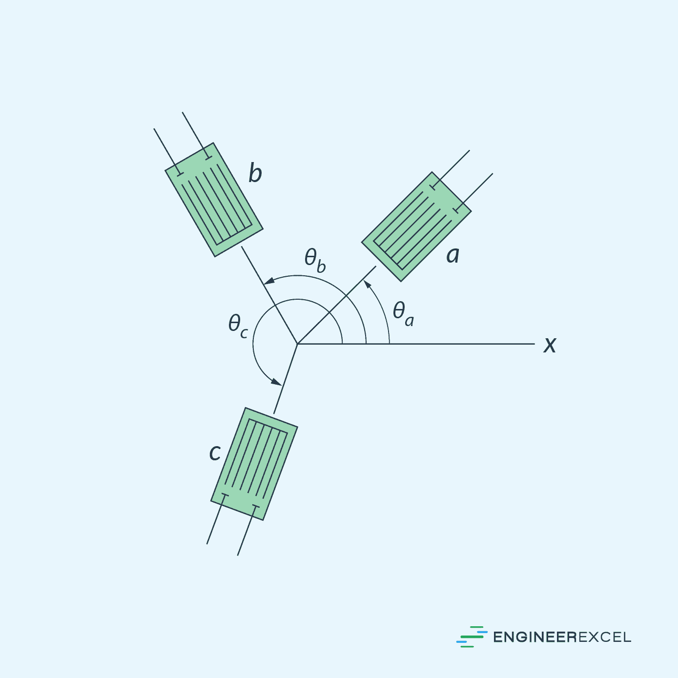
By taking axial strain readings ϵa, ϵb, and ϵc for each strain gauge, we can solve the following strain transformation equations simultaneously to determine the plane strain components (ϵx, ϵy, and γxy) at the point:
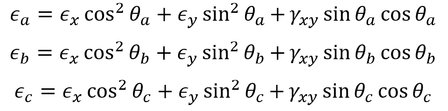
Where:
- ϵa, ϵb, ϵb = axial strain readings on each strain gauge [unitless]
- ϵx, ϵy = normal plane strain components along x and y axes [unitless]
- γxy = shear plane strain component [rad]
- θa, θb, θc = angle of each strain gauge with respect to the x axis [rad]
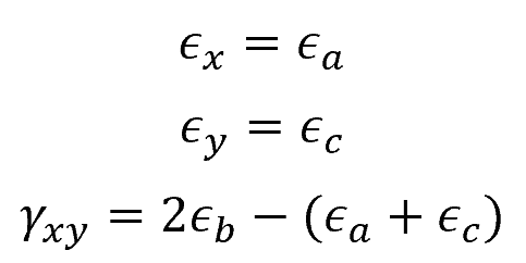
For a 45-degree rosette, the above set of equations can be simplified to:
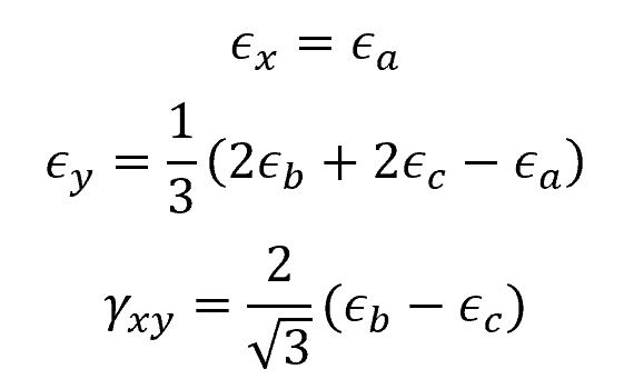
And for a 60-degree rosette:
After determining the values of the plane strain components (ϵx, ϵy, and γxy), we can use strain transformation equations to calculate for the principal in-plane strains:
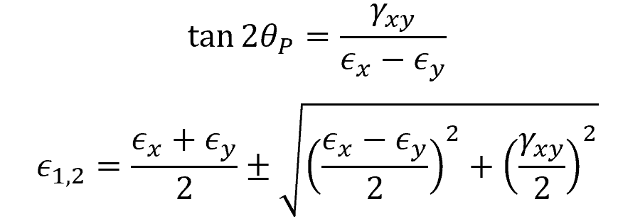
Where:
- θP = orientation of the plane of principal strain with respect to x axis [rad]
- ϵ1,2 = principal strains [unitless]
Similarly, the maximum in-plane shear strain can be calculated using the following equations:
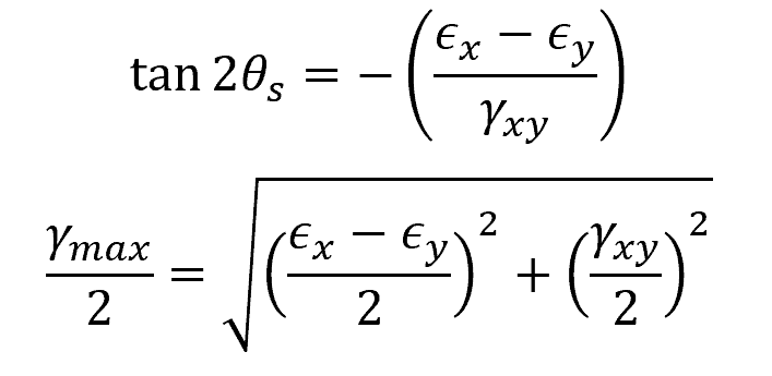
Where:
- θs = orientation of the plane of maximum shear strain with respect to x axis [rad]
- γmax = maximum in-plane shear strain [rad]