
FEATURED TORSION RESOURCES
[no_toc]
Shear Flow in Solid Mechanics
Torsion of Rectangular Sections: A Detailed Analysis
Torsion Formula: A Comprehensive Guide
Average Shear Stress: Formula and Practical Applications

Torsional Rigidity Explained
Polar Moment of Inertia Explained
Angle of Twist Formula for Shaft Design
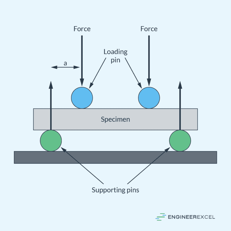
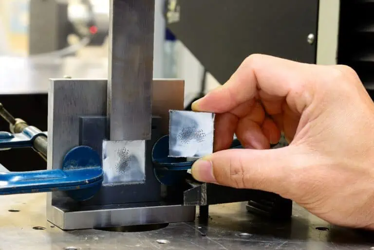
Flexural Strength: Key Factors and Measurement
Stresses in a Shaft: Understanding the Mechanics

Torsional Stiffness
Stepped Shaft Stress Concentration
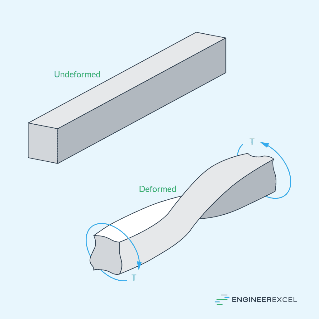
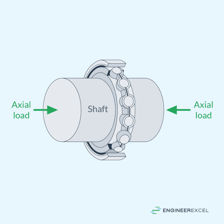
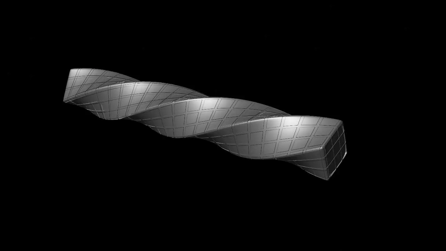
Torsion is a type of mechanical deformation experienced by an object when a twisting force is applied to it. In engineering, torsion is commonly observed in shafts and other cylindrical structures that are subjected to torque, resulting in angular displacement and shear stress.
In this article, we will discuss the fundamentals of torsion, including the torsion formula, angle of twist, torsional stiffness and rigidity, polar moment of inertia, stress analysis in torsion, and torsion in different geometries including rectangular sections and stepped shaft stress concentration.
Fundamentals of Torsion

Elevate Your Engineering With Excel
Advance in Excel with engineering-focused training that equips you with the skills to streamline projects and accelerate your career.
Defining Torsion
Torsion is a type of mechanical deformation experienced by an object when a twisting force, also known as torque, is applied to it. In engineering, torsion is commonly observed in shafts and other cylindrical structures that are subjected to torque. The object undergoes angular displacement and shear stress as a result of torsion.
Torsion Formula
The Torsion Formula relates shear stress to the applied torque and cross-sectional geometry of the object. It is derived based on the assumptions that the object’s cross-section remains plane during the application of torque, and shear strain varies linearly from the axis of the shaft to the extreme radius.
Considering these assumptions, the torsion equation can be expressed as follows:
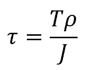
Where:
- τ = shear stress [Pa]
- T = applied torque [N-m]
- ρ = radial distance from the center of the shaft [m]
- J = polar moment of inertia [m4]
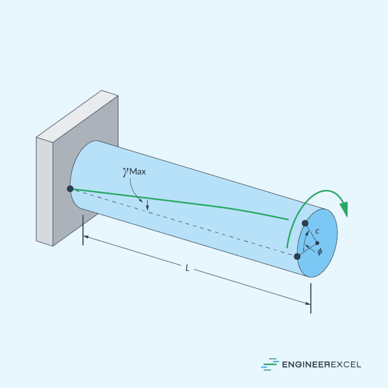
Angle of Twist
The angle of twist is an essential parameter in understanding torsional behavior. It quantifies the amount of angular deformation experienced by a member due to an applied torque.
The most common formula to calculate the angle of twist is:
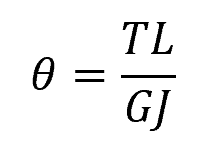
Where:
- θ = angle of twist (radians)
- L = length of the member (m)
- G = shear modulus of the material (Pa)
Using this formula, engineers can determine the expected deformation under a specific load and select appropriate materials or design parameters.
Mechanical Properties Influencing Torsion
Torsional Stiffness
Torsional stiffness is a measure of an object’s resistance to twisting when torque is applied. It is defined as the amount of radially applied torque required to twist an object by one radian unit.
Derived from the angle of twist equation, the formula for torsional stiffness can be written as:
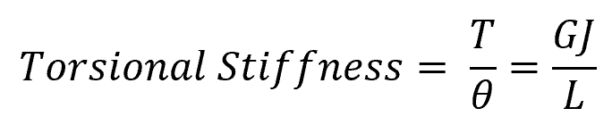
Where:
- θ = angle of twist (radians)
- G = modulus of rigidity [Pa]
- J = cross-sectional polar moment of inertia [m3]
The modulus of rigidity (G) is a material property that describes how resistant the material is to shear deformation and depends on the stress-strain relationship within the elastic deformation range.
Members with high torsional stiffness are less likely to deform under torque. This value is dependent on the length of the member. That is, a longer shaft would normally be less stiff than a shorter shaft and vice versa.
Torsional Rigidity
Another parameter used to measure the torsional resistance of a structural element is torsional rigidity. It is essentially the same as torsional stiffness, except that its value is independent of the length of the member, as shown by the following formula:
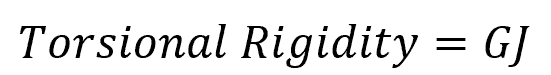
Members with different lengths but with the same material and cross-sectional geometry would have the same torsional rigidity.
Polar Moment of Inertia
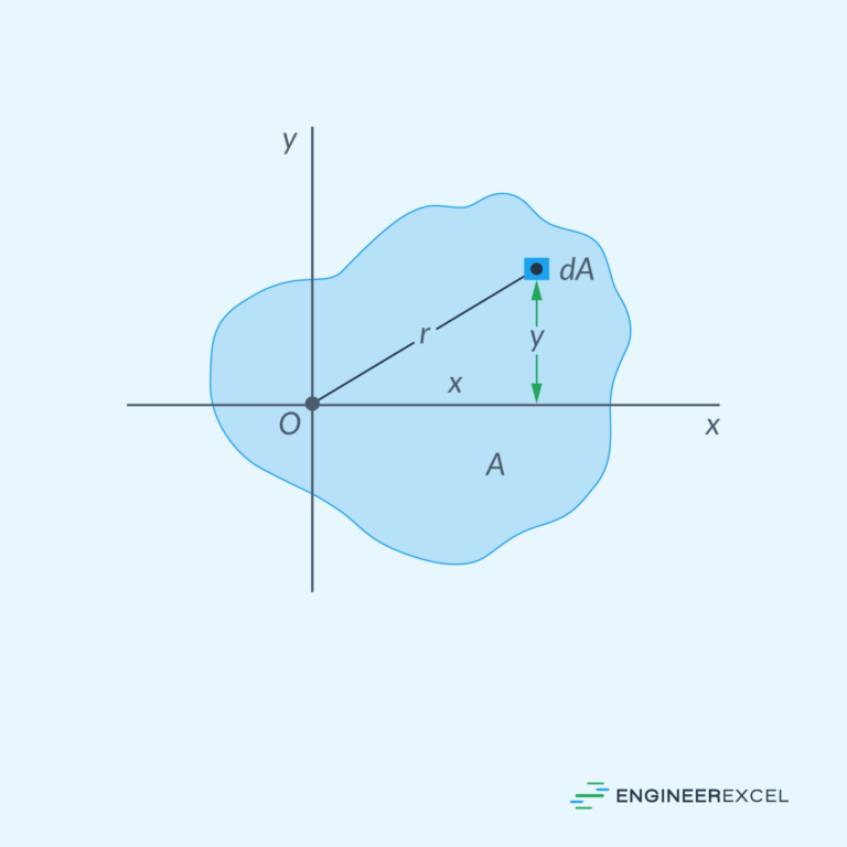
All of the parameters discussed above are affected by the polar moment of inertia— a parameter that quantifies an object’s resistance to torsion by characterizing its cross-sectional geometry.
To calculate the polar moment of inertia, you must integrate the square of the distance between each infinitesimal area, within the cross-sectional plane, and the center of rotation with respect to the entire area.
For some common shapes, the polar moment of inertia can be determined using formulas. For example, for a solid circular shaft, the polar moment of inertia is:
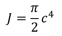
Where:
- c = radius of the shaft [m]
For a hollow circular shaft:
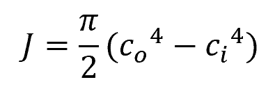
Where:
- co = outer radius of the shaft [m]
- ci = inner radius of the shaft [m]
In general, an object with a larger polar moment of inertia will have higher resistance to twisting. This is why engineers often select structural members with a high polar moment of inertia for applications subject to significant torsion loads.
Stress Analysis in Torsion
Stresses in a Shaft
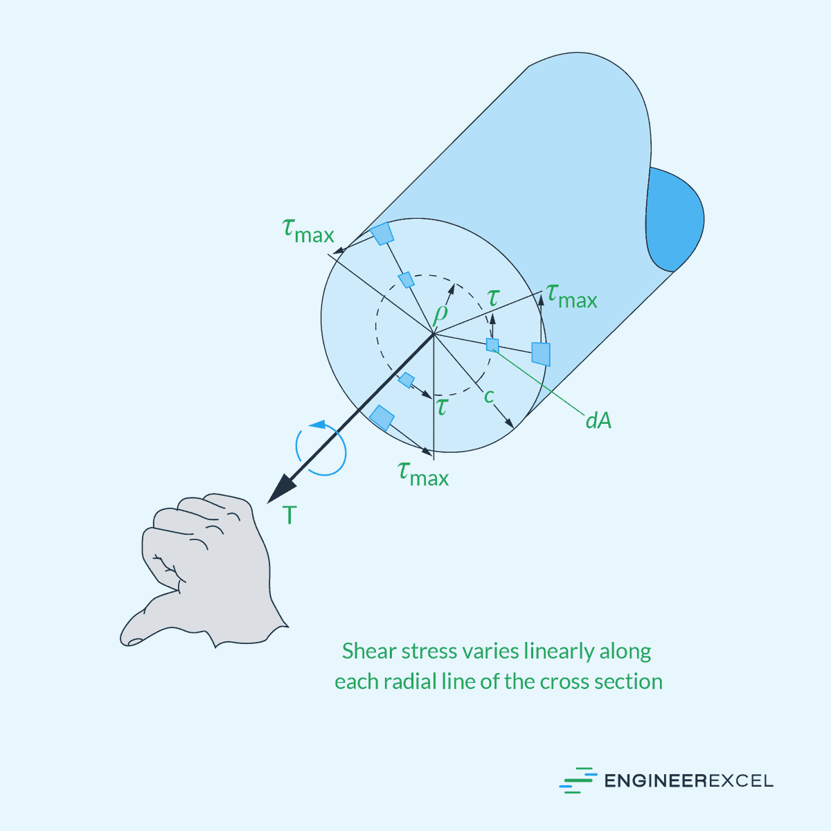
In torsion problems, the primary stresses that develop within a shaft are shear stresses. When a torque is applied to a shaft, the internal shear stresses counteract the applied torque.
The shear stress distribution in a circular shaft is not uniform. According to the Torsion Formula, shear stress varies linearly from zero at the center to a maximum value at the outer surface, as shown in the diagram below.
Average Shear Stress
For thin-walled tubes, however, it is more practical to assume that shear stress is uniformly distributed across the thickness of the tube at any given point.
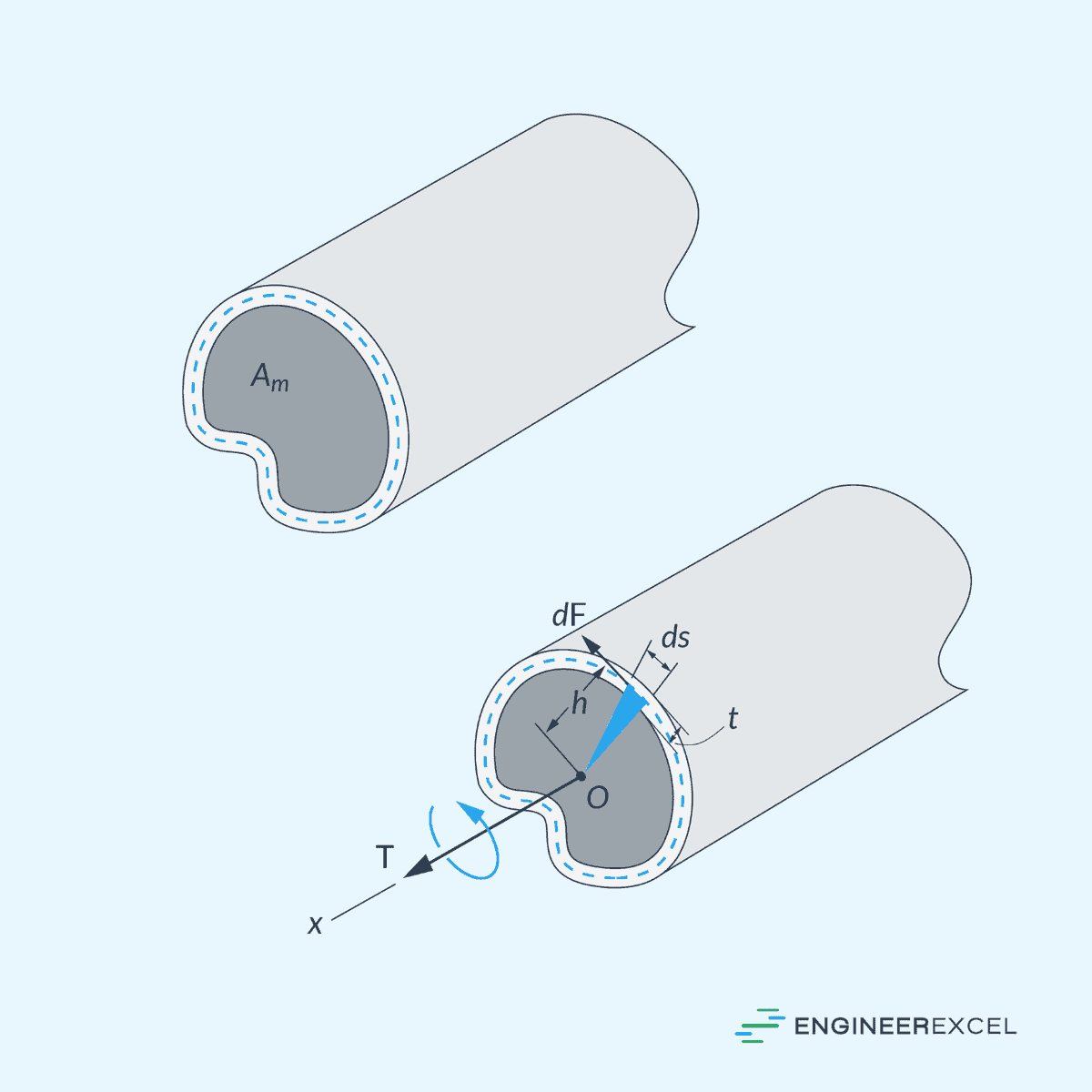
In this case, the average shear stress can be calculated using the formula:
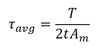
Where:
- τavg = average shear stress [Pa]
- t = thickness of the tube [m]
- Am = mean area enclosed within the boundary of the centerline of the tube’s thickness [m2]
where T is the applied torque, r is the radius of the shaft, and J is the polar moment of inertia.
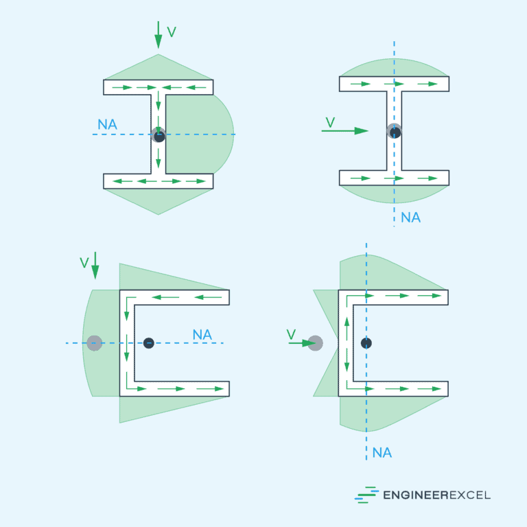
Shear Flow
In thin-walled tubes, the product of the average shear stress times the thickness of the tube is the same at each point on the tube’s cross-sectional area. This product is called shear flow, which can be expressed as:

Where:
- q = shear flow [N/m]
Since shear flow is constant over the cross section, the maximum shear stress must occur where the tube’s thickness is the smallest.
Torsion in Different Geometries
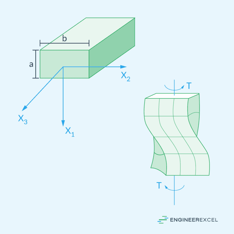
Torsion of Rectangular Sections
Shafts with rectangular sections are not axisymmetric. Hence, when torsion is applied, their cross sections tend to distort. This warping results in additional stresses and strains within the material, making the analysis more complex than circular shafts.

In this case, the torsion formula can be transformed by considering an equivalent polar section modulus, such that:
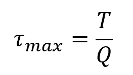
Where:
- τmax= maximum torsional shear stress [Pa]
- Q = equivalent polar section modulus [m3]
For a solid rectangular section, the equivalent polar section modulus can be calculated using the following formula:
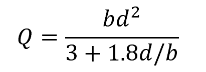
Where:
- b = longer side of the rectangular cross-section [m]
- d = shorter side of the rectangular cross-section [m]
For a thin-walled hollow rectangular section with smooth corners:
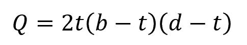
Where:
- t = uniform thickness of the rectangular walls [m]
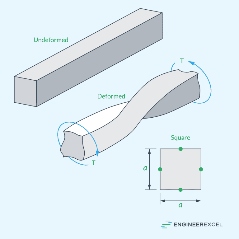
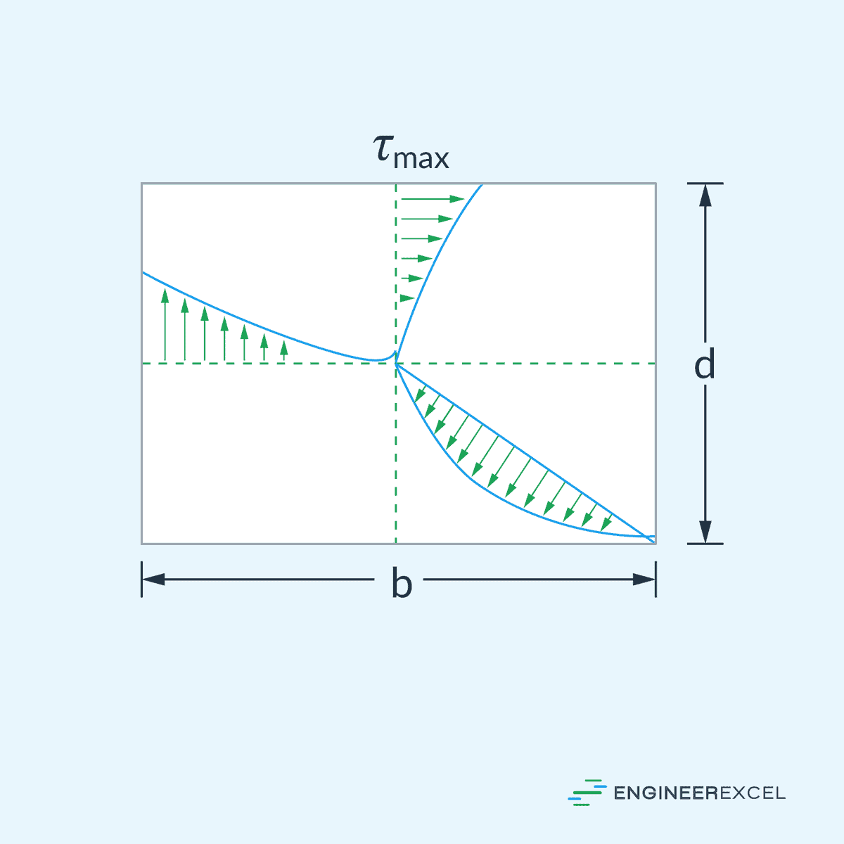
Unlike circular sections, the torsional shear stress in rectangular sections varies nonlinearly across the cross section and the maximum torsional shear stress occurs at the midpoint of the longer sides.
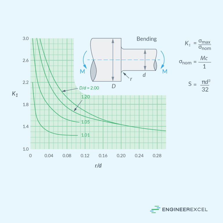
Stepped Shaft Stress Concentration
In stepped shafts, variations in cross-sectional shapes or sizes can produce stress concentrations or areas with increased stress levels.
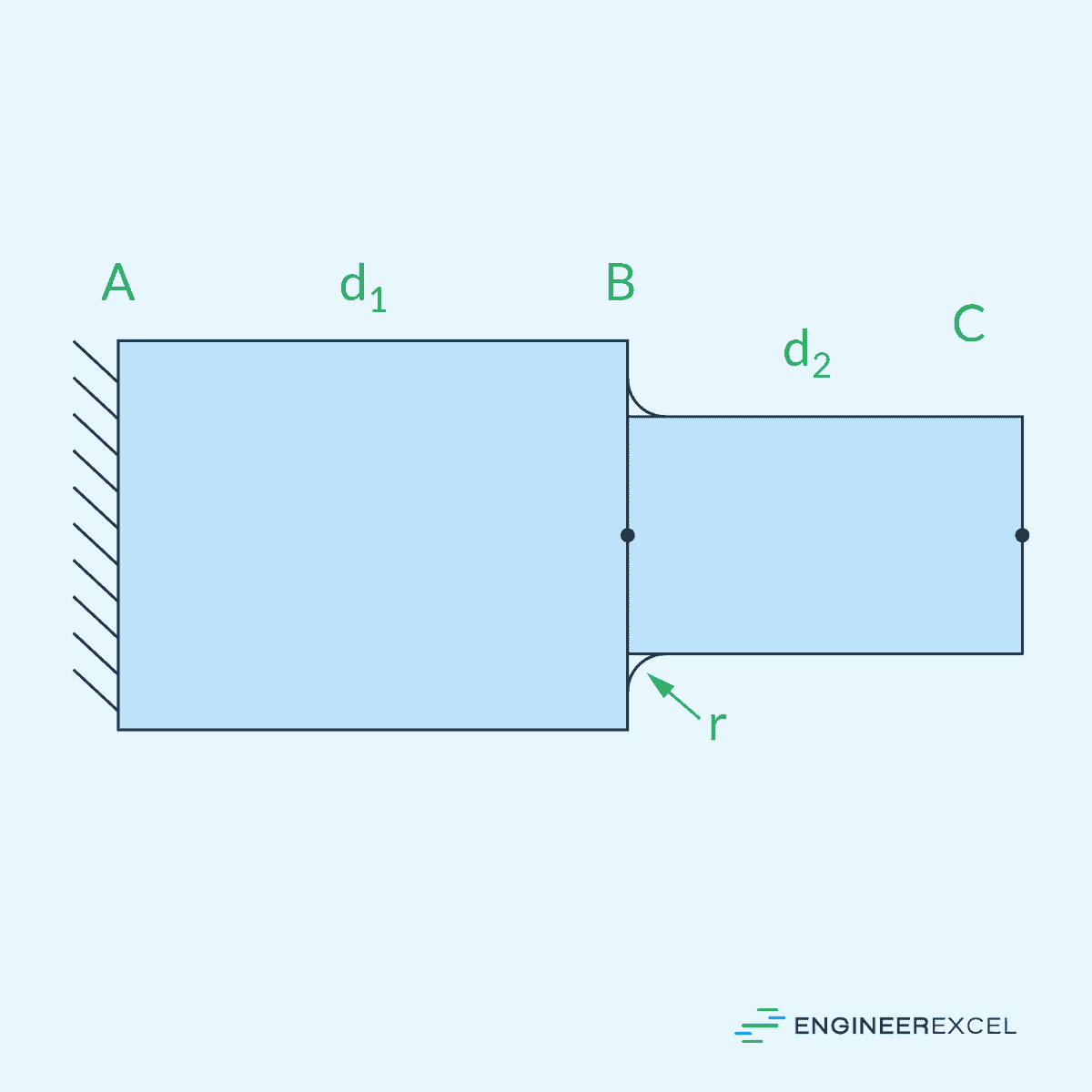
Stress concentration is quantified using stress concentration factor, which is defined as the ratio of the maximum stress at the location of step to the nominal stress. For shafts under torsion, it can be calculated as follows:
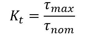
- τmax = maximum torsional shear stress at the location of the step [Pa]
- τnom = nominal torsional shear stress [Pa]