
Torsion stress is a type of shear stress that occurs in objects with an applied torque. It is particularly relevant in the design and analysis of various engineering components, such as shafts, axles, and springs, where twisting or rotational forces are significant.
In this article, we will discuss torsion stress in various geometries, including circular and non-circular solid shafts, as well as thin-walled tubes.
Torsion Stress Explained
Torsion stress refers to the stress experienced by an object when twisted. It is characterized by a shearing action within the material, as adjacent layers or particles of the material slide past one another in response to the applied torque. This type of stress is commonly found in mechanical components that undergo rotational motion, such as shafts, screws, torsion springs, and propeller blades.
The impact of torsion stress on materials depends on their inherent properties and resistance to shape change. Depending on magnitude, it may undergo elastic deformation, where it returns to its original shape after the applied torque is removed. However, when the torsional stress exceeds the material’s elastic limit, it may enter the plastic deformation region.

Elevate Your Engineering With Excel
Advance in Excel with engineering-focused training that equips you with the skills to streamline projects and accelerate your career.
Continuous exposure to extreme torsional stress can result in material fatigue, leading to permanent damage or failure of the component. Hence, understanding the mechanics of torsion stress is important in engineering design.
Torsion stress is spread unevenly within an object. In general, it varies with the distance from the axis of rotation.
However, the specific distribution of torsion stress varies depending on shaft geometry. Circular cross-sections, for instance, can distribute torsional loads more evenly, reducing the likelihood of stress concentration and failure.
The following sections discuss torsion stress in different shaft geometries.
Torsion Stress Calculation in Circular Shafts
When a circular shaft is subjected to torsion, the stress within the shaft is not evenly distributed. Instead, it varies linearly along each radial line of the cross section. The maximum shear stress occurs at the outer surface of the shaft and decreases linearly with the radial distance toward the center of the shaft, as shown in the diagram below.

The formula to calculate the shear stress due to torsion in a circular shaft is given by:
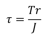
Where:
- τ = torsional shear stress [Pa]
- T = applied torque [N-m]
- r = radial distance from the center of the shaft [m]
- J = polar moment of inertia [m4]
The polar moment of inertia depends on the shaft geometry. For solid circular shafts:
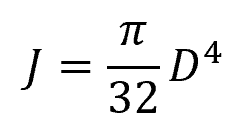
Where:
- D = shaft diameter [m]
And for hollow shafts:
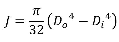
Where:
- Do = outer shaft diameter [m]
- Di = inner shaft diameter [m]
Note that circular shafts generally experience other types of stresses aside from torsional stress, for example, normal stress due to bending and vertical shearing stress. When designing shafts, it is important to account for all of these stresses.
Torsion Stress Calculation in Non-Circular Solid Shafts
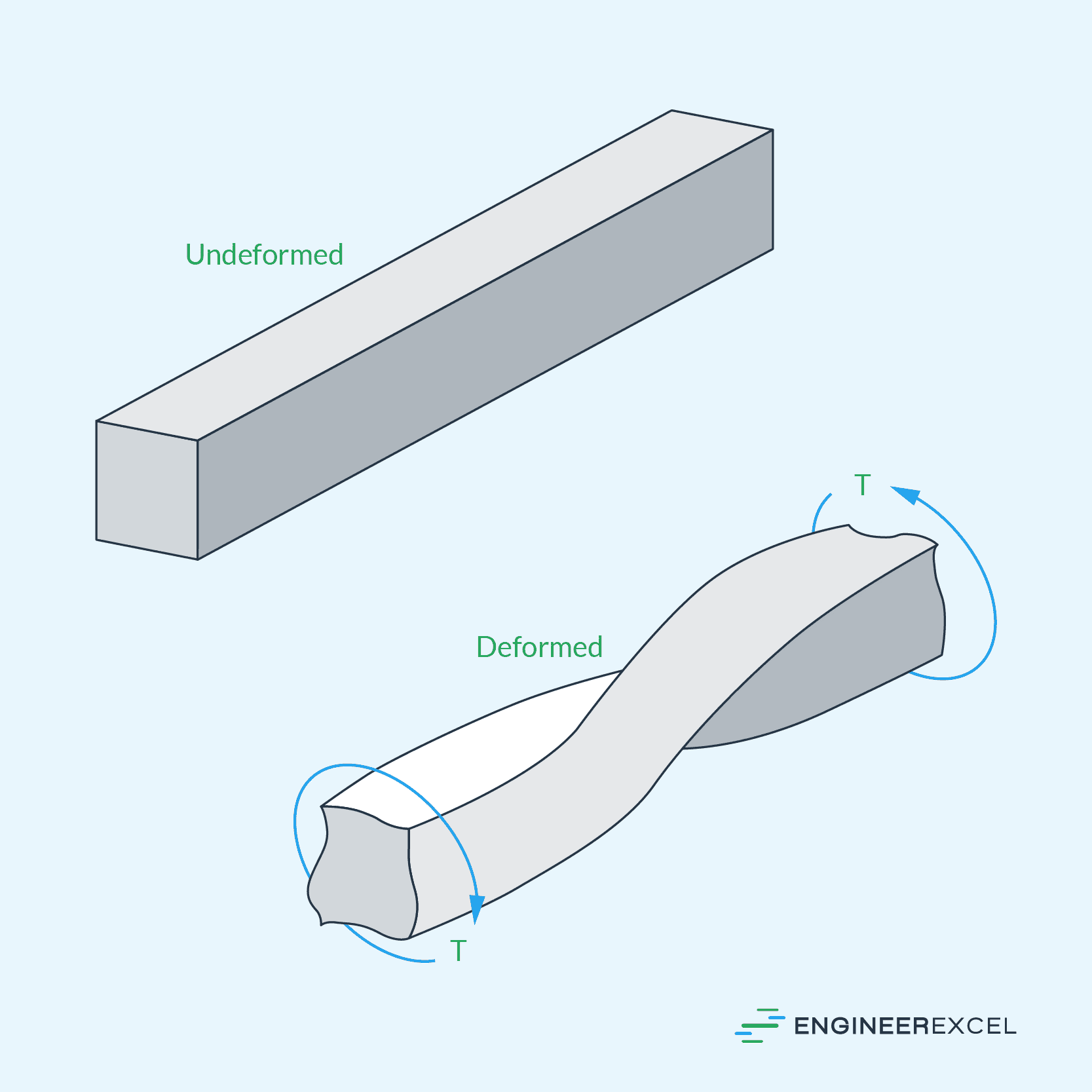
Non-circular cross-sections are more susceptible to warping compared to circular cross-sections. Warping refers to the deformation of the shaft’s cross-sectional geometry under torsion load, which can result in additional stress distribution complexities.
Hence, calculating torsion stress in non-circular solid shafts requires a different approach compared to circular shafts. Non-circular shafts involve more complex shear stress distributions. To analyze these shafts, a combination of numerical and analytical approaches can be applied based Saint-Venant’s principle.
Saint Venant’s principle states that, for non-circular cross-sectional shapes under pure torsion, the stresses and strains become uniform within a certain distance from the applied torque or twist. Beyond this distance, the stress and strain distributions become asymptotically constant, and the torsional effects are effectively localized to the immediate vicinity of the applied load.
This principle simplifies the analysis of torsion in non-circular sections by allowing engineers to focus on the area near the applied load, where the stress and strain distributions are more easily determined. It helps in solving complex engineering problems involving torsion in non-circular members by providing a framework for approximating the stress and deformation behavior.
However, explicit solutions for non-circular shafts of common cross-sections have been developed. For example, the table below summarizes the formulas for calculating the maximum torsional shear stress of shafts with square, triangular, and elliptical cross-sections:
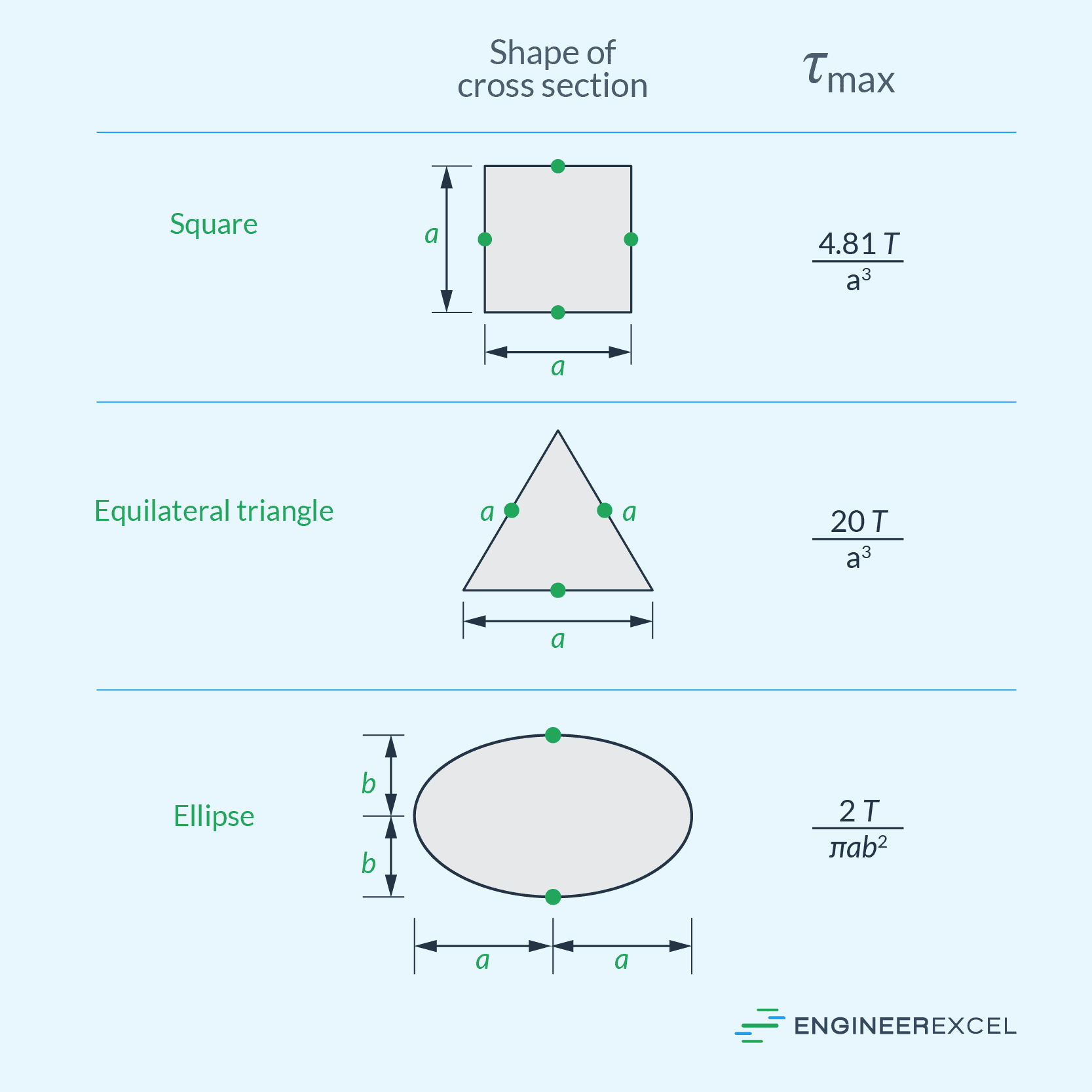
In all of the mentioned cross-sections, the maximum shear stress happens at a point on the edge of the cross section closest to the center axis of the shaft.
Torsion Stress Calculation in Thin-Walled Tubes
Thin-walled tubes with noncircular cross sections are commonly used to create lightweight frameworks for aircraft and other applications. When these tubes are subjected to torsional loading, the product of the average shear stress and the thickness of the tube remains constant across the tube’s cross-sectional area. Hence, the smallest thickness of the tube corresponds to the largest average shear stress.
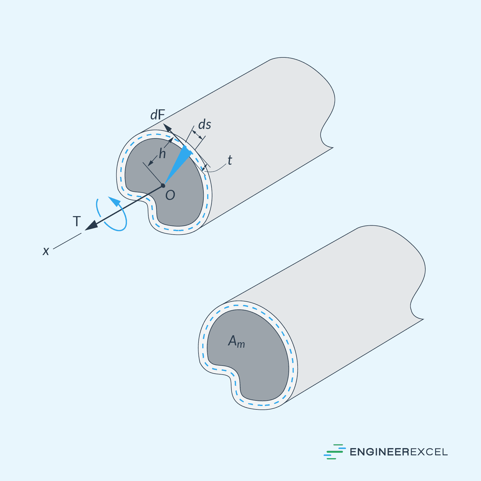
The applied torque causes the shear stress to be directed tangent to the tube’s wall. To calculate the average shear stress over a specific thickness of the tube, the following formula can be used:
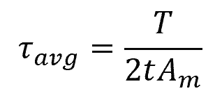
Where:
- τavg = average shear stress [Pa]
- T = resultant internal torque at the cross-section [N-m]
- t = thickness of the tube [m]
- Am = mean area enclosed within the centerline of the tube’s thickness [m2]
Example Problem
Problem: A cylindrical shaft is subjected to a torque of 500 Nm. The shaft has a diameter of 50 mm and a length of 1 meter. Determine the maximum torsional shear stress.
Solution:
First, calculate the polar moment of inertia:
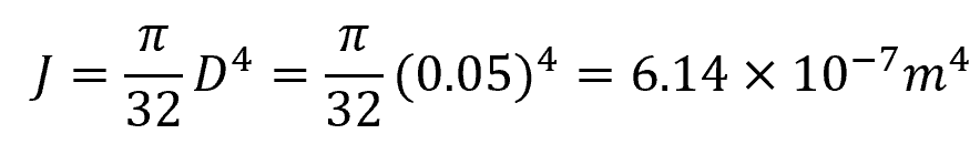
Then calculate the maximum torsional shear stress using the radius of the shaft:
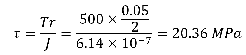
The maximum torsional shear stress at the surface of the shaft is equal to 20.36 MPa.