
The Torsion Formula is a fundamental equation used to analyze the stresses in a structural member subjected to torsional loads. It relates the internal torque applied to the member to the resulting shear stress at any point along the length of the member. In this article, we discuss the torsion formula as well as its derivation, application, and limitations.
What is the Torsion Formula
When an external torque is applied to a shaft, it generates an internal torque within the shaft. The Torsion Formula is an equation that relates this internal torque to the distribution of shear stress on the cross section of the shaft. This formula is useful for designing and analyzing mechanical components like shafts, gears, and propeller blades.
Derivation of the Torsion Formula
If the shaft material is linear-elastic, then Hooke’s law applies:

Elevate Your Engineering With Excel
Advance in Excel with engineering-focused training that equips you with the skills to streamline projects and accelerate your career.
Where:
- τ = shear stress [Pa]
- G = shear modulus of the shaft material [Pa]
- γ = shear strain [unitless]
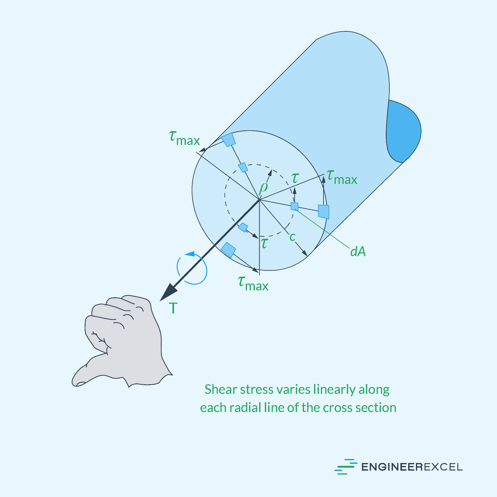
As a result, a linear change in shear strain causes an equivalent linear change in shear stress along any radial line on the cross section. This means that the shear stress will start from zero at the shaft’s longitudinal axis and increase to its maximum value at the outer surface, as shown in the diagram below.
The maximum shear stress due to torsion at the outer surface of the shaft can be calculated using the following formula:
Where:
- τmax = maximum shear stress due to torsion [Pa]
- T = applied torque [N-m]
- c = shaft radius [m]
- J = polar moment of inertia of the cross-sectional area [m4]
The above equation is often referred to as the torsion formula. To calculate the shear stress at an intermediate distance from the center, the torsion formula can be transformed as follows:
Where:
- τ = torsional shear stress at an intermediate distance from the center [Pa]
- ρ = radial distance from the center of the shaft [m]
Note that for a solid circular shaft, the polar moment of inertia can be calculated using the formula:
On the other hand, for a tubular shaft, the polar moment of inertia is equal to:
Where:
- co = outer radius of the shaft [m]
- ci = inner radius of the shaft [m]
Limitations to the Torsion Formula
The torsion formula discussed above is only generally applicable to circular shafts with a uniform cross-sectional area and made of isotropic material. It does not accurately predict the stress distribution in shafts with non-circular cross-sections or those with varying material properties.
Moreover, the formula assumes that linear elasticity is maintained throughout the entire loading process. If the stress levels reach beyond the elastic limit of the material, the formula no longer provides accurate results.
It is also assumed that the shear modulus remains constant throughout the entire shaft. However, in cases where the modulus varies with respect to the shaft length, a more complex analysis would be required.
Torsion Formula for Non-Circular Shafts
Torsion formula for non-circular shafts is more complex than the formula for circular shafts, primarily because non-circular cross-sections necessitate considering additional factors, such as warping.
An example of a non-circular shaft is a square shaft under torsion, as shown in the diagram below.
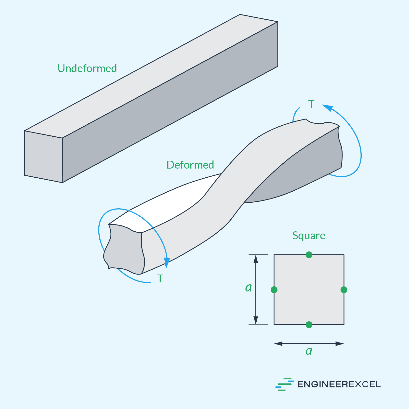
In this case, the maximum shear stress typically occurs at the edge of the cross-section closest to the shaft’s central axis. It can be described by the equation:
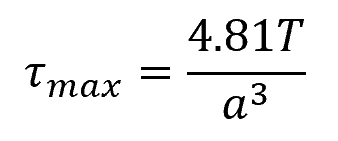
Where:
- a = length of one side [m]
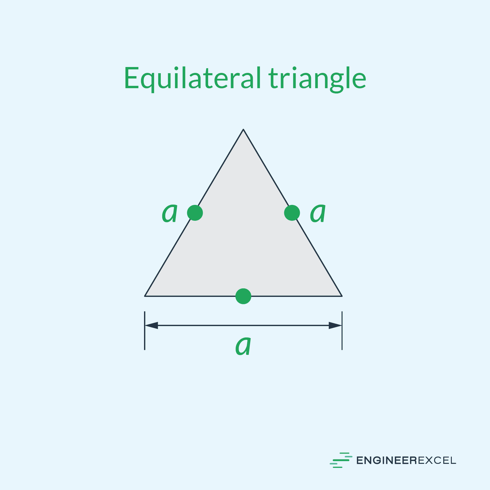
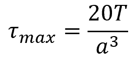
For a shaft with an equilateral triangle cross-section, the maximum shear stress can be calculated using the formula:
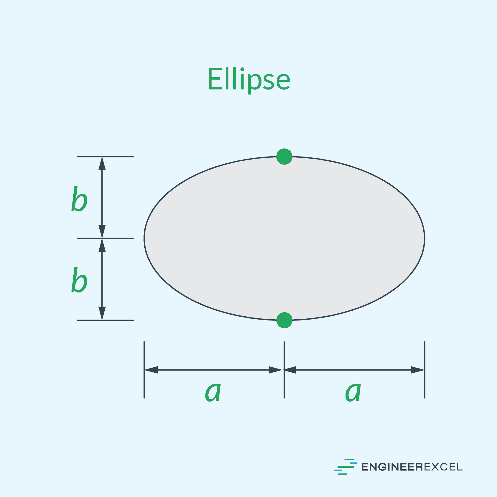
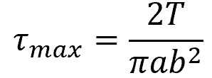
For a shaft with an elliptical cross-section, the maximum shear stress can be calculated using the formula:
Intermediate torsional support can be given by secondary framing components to help reduce the effect of torsion on non-circular cross-section members. When such support is provided, the warping effect can be diminished, resulting in a more manageable torsional load on the member.
Example Problem
Problem Statement: Consider a solid cylindrical bar with a circular cross-section subjected to torsion. The bar has a length of 10 m, a radius of 1 m, and is made of a homogeneous, isotropic material with shear modulus of 50 GPa. A torque of 50 kN-m is applied at one end, and the other end is fixed. What is the maximum shear stress in the bar?
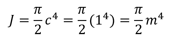
Answer: For this problem, we can first find the solid circular shaft’s polar moment of inertia using the following equation:
Then we use the torsion formula as follows:
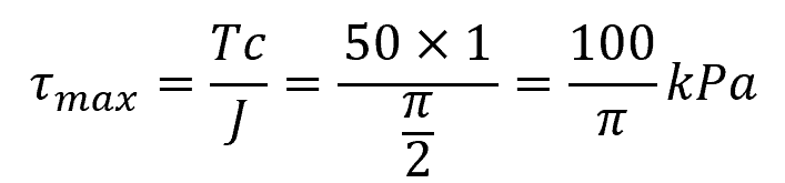
Therefore, the maximum shear stress experienced by the bar is equal to 100/π or approximately 31.8 kPa.