
When a shaft or beam with a rectangular cross-section undergoes twisting, it experiences non-uniform deformation along its cross-section due to the shearing action applied to its material. This type of deformation is a result of the torsional stress that occurs when torque is applied to the shaft or beam.
In this article, we will discuss the torsion of rectangular sections, including the distribution and calculation of torsional stress and angle of twist.
Understanding Torsion of Rectangular Sections
Torsion, the twisting of a structural member due to applied torque, is commonly associated with circular shafts, such as those found in drive shafts, screws, and axles. However, torsion can also occur in rectangular members. This is because when a force or torque is applied at a distance from the center of the member, it induces shear stresses that cause the member to twist.
The distribution of torsional stress in rectangular sections differs significantly from that of circular shafts. In circular shafts, the shear strains exhibit a linear variation from zero at the center to their maximum value at the outer surface. Moreover, since the shear strains remain uniform at all points on the same radius, the cross sections do not deform and maintain their planarity.

Elevate Your Engineering With Excel
Advance in Excel with engineering-focused training that equips you with the skills to streamline projects and accelerate your career.
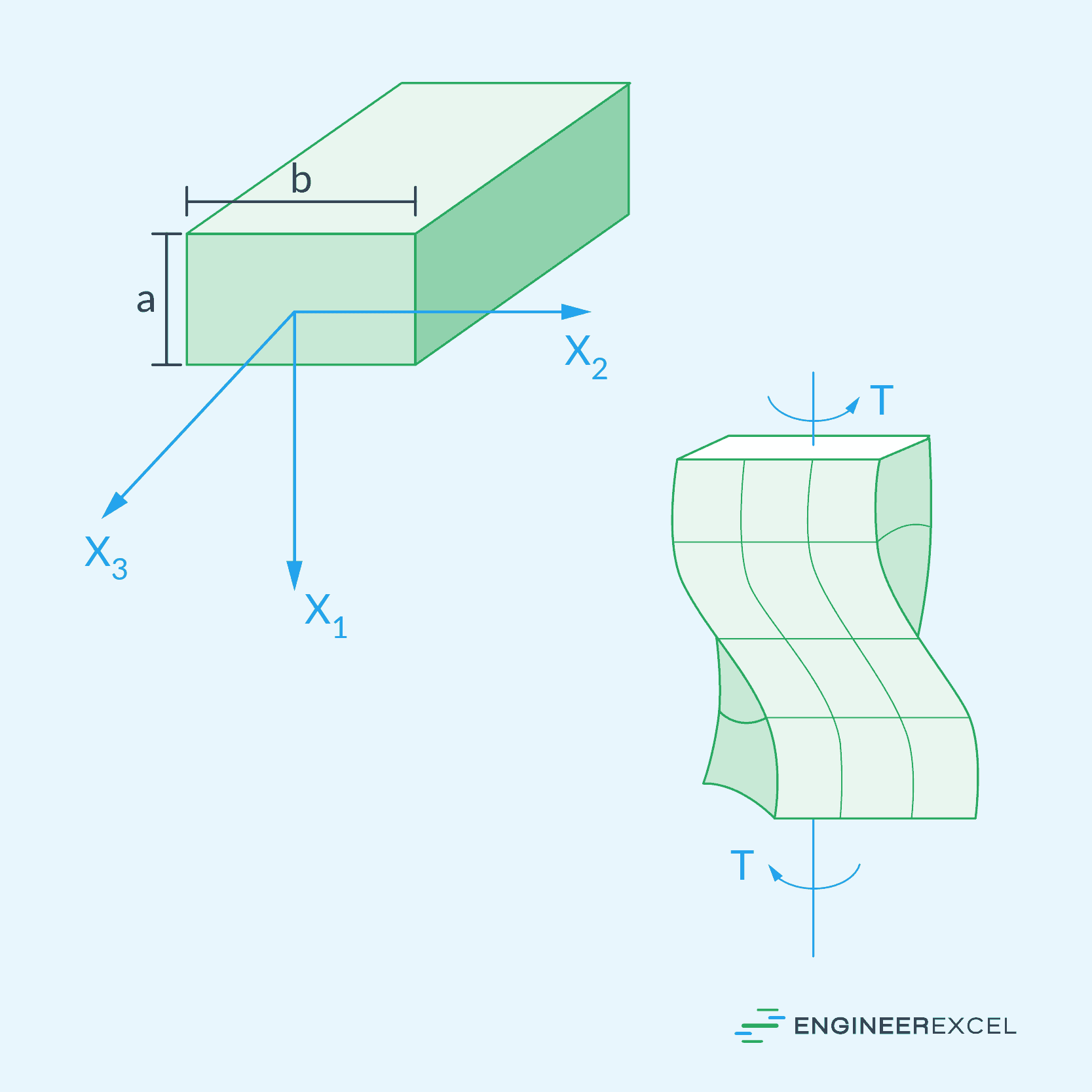
In contrast, shafts with rectangular sections are not axisymmetric, which leads to a distortion of their cross sections when torsion is applied. This warping or bulging effect can be observed by examining how grid lines on a rectangular cross-sectional shaft deform during the twisting process, as shown in the following diagram.
One common application of rectangular members subjected to torsion is in the design of beams and structural frames. Torsion can occur when external forces, such as wind or seismic loads, cause twisting moments in these structures. By understanding and analyzing torsional effects in rectangular members, engineers can optimize their designs to ensure structural integrity and safety.
Torsion Calculations for Rectangular Sections
The warping of cross-sectional planes that occurs in rectangular sections can result in additional stresses and strains within the material, making the analysis much more complex than circular shafts. In general, calculations can be done using numerical analysis, but there are also empirical formulas that can be used to approximate important parameters, such as torsional shear stress and angle of twist.
Torsional Shear Stress
In general, the maximum torsional shear stress for any non-circular cross-section can be calculated using the following formula:
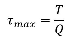
Where:
- τmax= maximum torsional shear stress [Pa]
- T = applied torque [N-m]
- Q = equivalent polar section modulus [m3]
For a solid rectangular section, the value of the equivalent polar section modulus is:
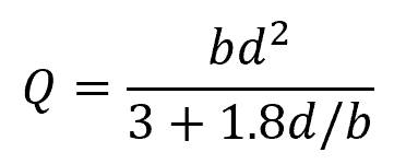
Where:
- b = longer side of the rectangular cross-section [m]
- d = shorter side of the rectangular cross-section [m]
For a thin-walled hollow rectangular section with smooth corners:
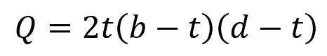
Where:
- t = uniform thickness of the rectangular walls [m]
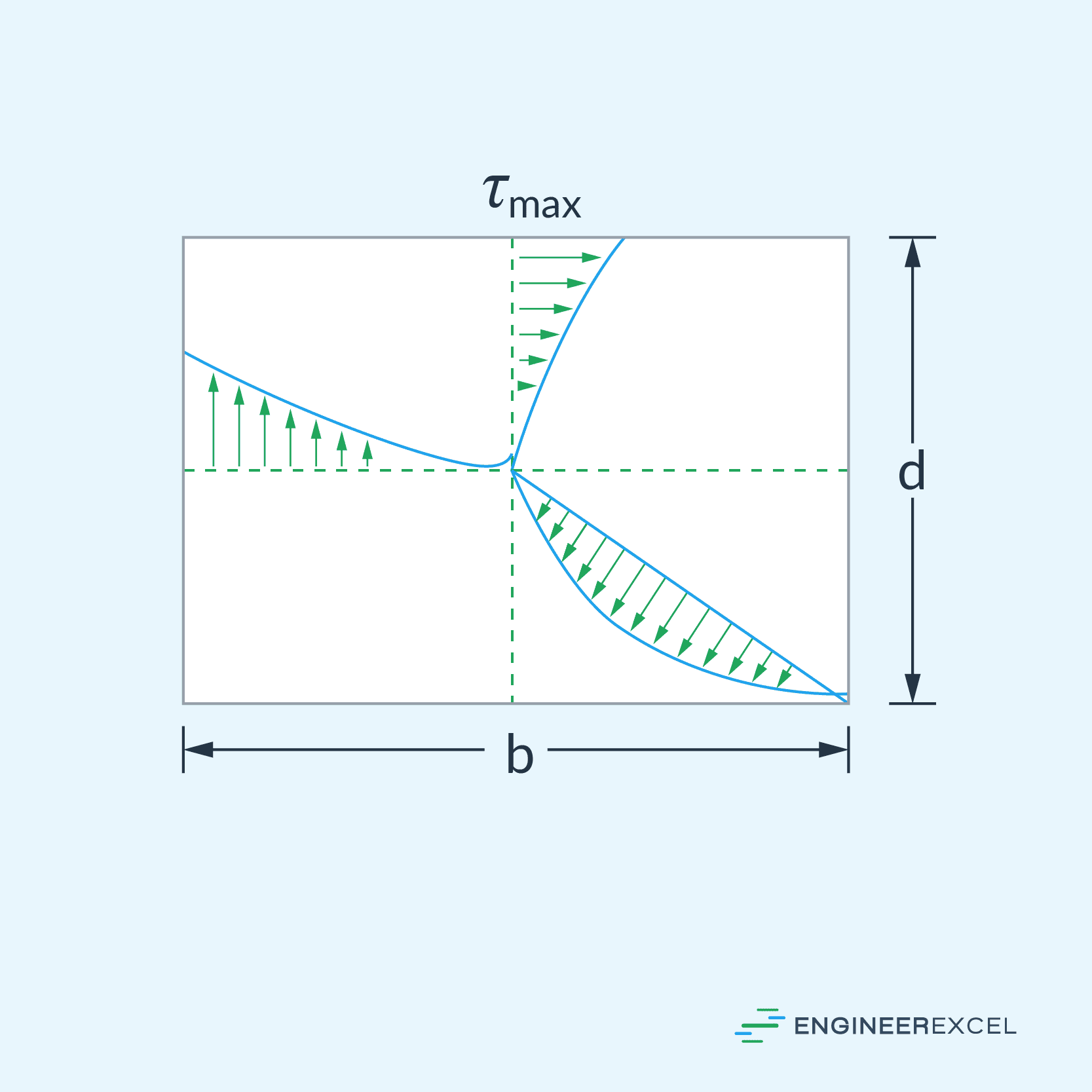
Note that, for rectangular sections, the torsional shear stress varies nonlinearly across the cross-sectional area, as shown in the diagram below. In this case, the maximum torsional shear stress typically occurs at the midpoint of the longer sides.
Angle of Twist
The angle of twist represents the rotation of the cross-section due to torsion along its longitudinal axis. In general, the angle of twist for any non-circular cross-section can be calculated using the following formula:
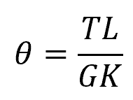
Where:
- θ = angle of twist [radians]
- L = length of the member [m]
- G = shear modulus of the material [Pa]
- K = equivalent polar moment of inertia [m4]
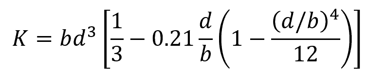
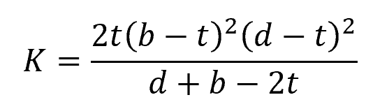
For a solid rectangular section, the value of the equivalent polar moment of inertia is:
For a thin-walled hollow rectangular section with smooth corners:
Example Problem
Problem: A rectangular beam with a width of 200 mm and a height of 100 mm is subjected to a torque of 50 Nm. Determine the maximum torsional shear stress in the beam.
Solution: Given, width (b) = 200 mm, height (d) = 100 mm, torque (T) = 50 Nm.
First, we need to calculate the value of the equivalent polar section modulus using the formula:
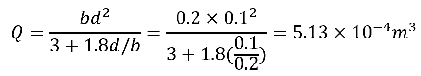
Now, we can calculate the maximum torsional shear stress using the formula:
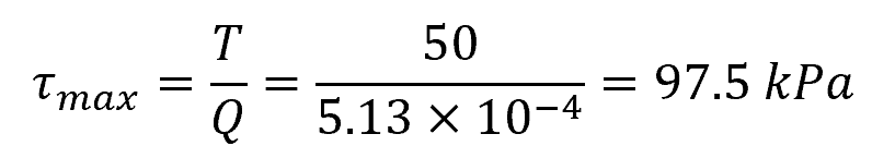
Therefore, the maximum torsional shear stress in the rectangular section beam is 97.5 kPa. Note that this occurs at the midpoint along the edge of the 200-mm width of the section.