
Shaft stress refers to the internal forces acting on a shaft during operation. Understanding the mechanics of stresses in a shaft is essential for engineers to design reliable and durable shaft systems.

In this article, we will discuss the different types of stresses that can occur in a shaft, how to calculate them, the causes of stress concentrations in shafts, and the various methods used to analyze shaft stresses.
What is Shaft Stress
Shaft stress refers to the internal forces acting on a shaft. A shaft is typically a cylindrical object that transmits torque or motion. They often function as essential components in machinery, such as gears, pulleys, and motors.
Stresses on a shaft can be caused by various factors, depending on the type and configuration of loading involved. Understanding their nature is essential for engineers to design reliable and durable components.

Elevate Your Engineering With Excel
Advance in Excel with engineering-focused training that equips you with the skills to streamline projects and accelerate your career.
If not properly managed, excessive stress can lead to various issues, such as deformation or failure of the shaft. For this reason, it is vital to analyze and reduce stresses in shafts through appropriate design and material selection.
Types of Stresses in a Shaft
Shafts encounter different types of stresses during operation. The primary types include Torsional Shear Stress, Bending Stress, Direct Shear Stress, and Axial Stress.
Torsional Shear Stress
Torsional shear stress is the stress induced in a shaft when it is subjected to torque, causing it to twist along its axis. This is commonly encountered in various mechanical, such as in the design of drive shafts, transmission shafts, and other rotating components.
The torsional shear stress can be calculated using the following formula:
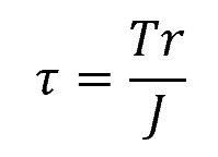
Where:
- τ = torsional shear stress [Pa]
- T = applied torque [N-m]
- r = radial distance from the shaft’s axis [m]
- J = polar moment of inertia of the shaft’s cross-sectional area [m4]
In the case of a solid circular shaft, the polar moment of inertia can be calculated as:
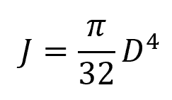
Where:
- D = diameter of the shaft [m]
For a hollow circular shaft:
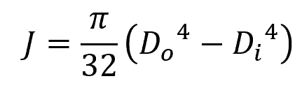
Where:
- Do = outer diameter of the shaft [m]
- Di = inner diameter of the shaft [m]
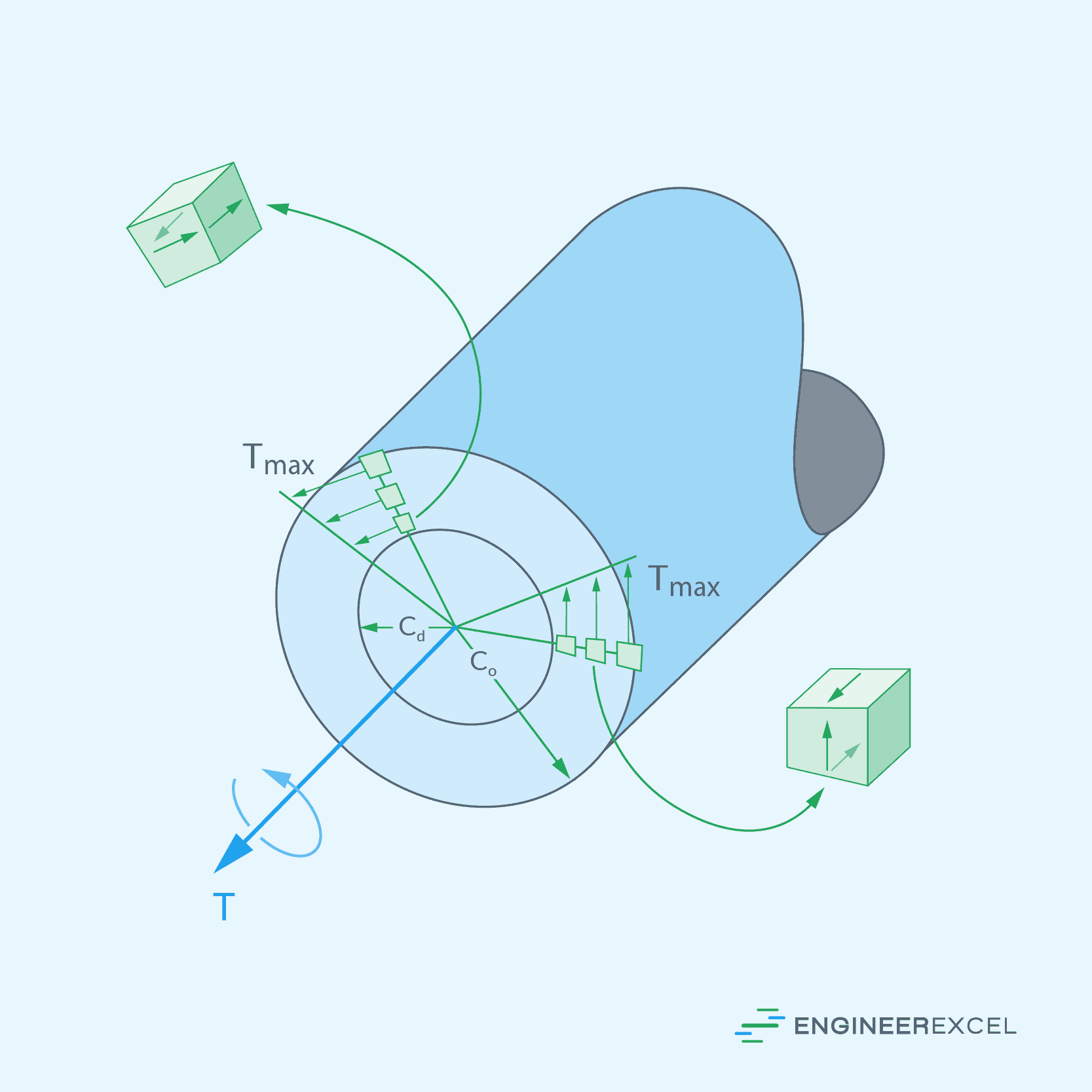
Note that the torsional shear stress is maximum at the outer surface and decreases linearly to zero at the center, as shown in the diagram below.
Aside from the torsional shear stress, it is essential to consider the torsional deformation and angle of twist under applied torque, as it can affect the functional performance of the shaft and connected components.
Bending Stress
Bending stress occurs when a shaft is subjected to a bending moment, causing it to bend or experience deflection. Bending moment arises from loads and forces acting perpendicular to the shaft’s axis. Bending stresses are particularly critical in gear transmission, drive systems, and structures supporting loads.
The bending stress in the shaft can be calculated using the following formula:
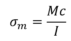
Where:
- σm = normal stress due to bending [Pa]
- M = bending moment [N-m]
- c = distance from the neutral axis to the outer fiber [m]
- I = moment of inertia [m4]
For a circular cross-section, the moment of inertia can be calculated as follows:
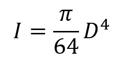
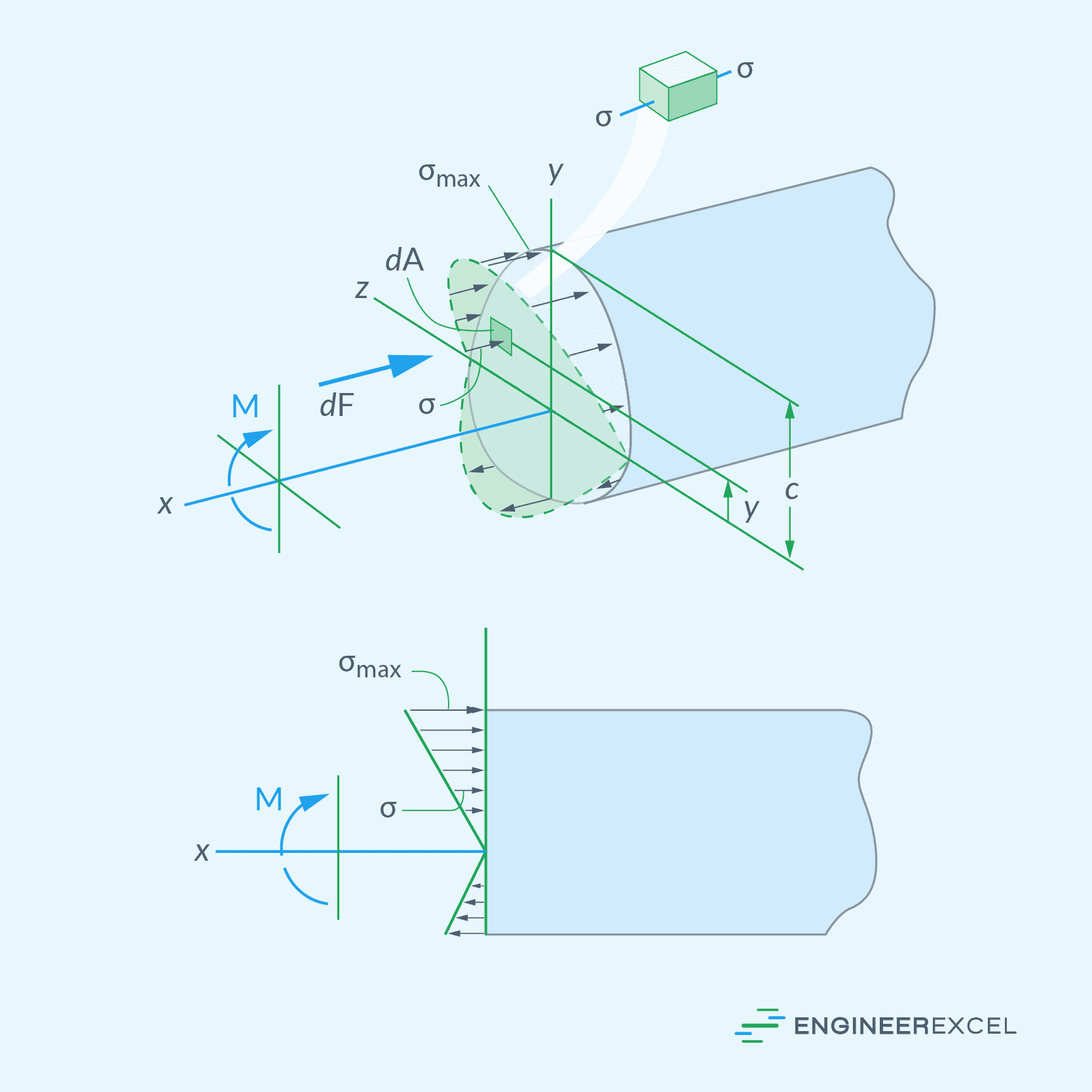
Note that a shaft under bending stress experiences both tensile and compressive stresses along its cross-section, depending on the orientation of the bending moment applied. The magnitude of these stresses increases as you move farther away from the neutral axis, as shown in the diagram below.
Vertical Shearing Stress
Vertical shearing stress is the stress that acts perpendicular to the axis of a shaft and tries to shear or ‘slide’ the material planes of the shaft against each other. This become important to the design analysis in instances where torque is not applied and the bending moments are low or negligible, such as when a shaft is supported by a bearing at its end and not transmitting torque.
The maximum shearing stress occurs at the neutral axis of the shaft, as shown in the diagram below. From the neutral axis, the shearing stress decreases approximately in a parabolic pattern until it reaches zero at the outer surface of the shaft.
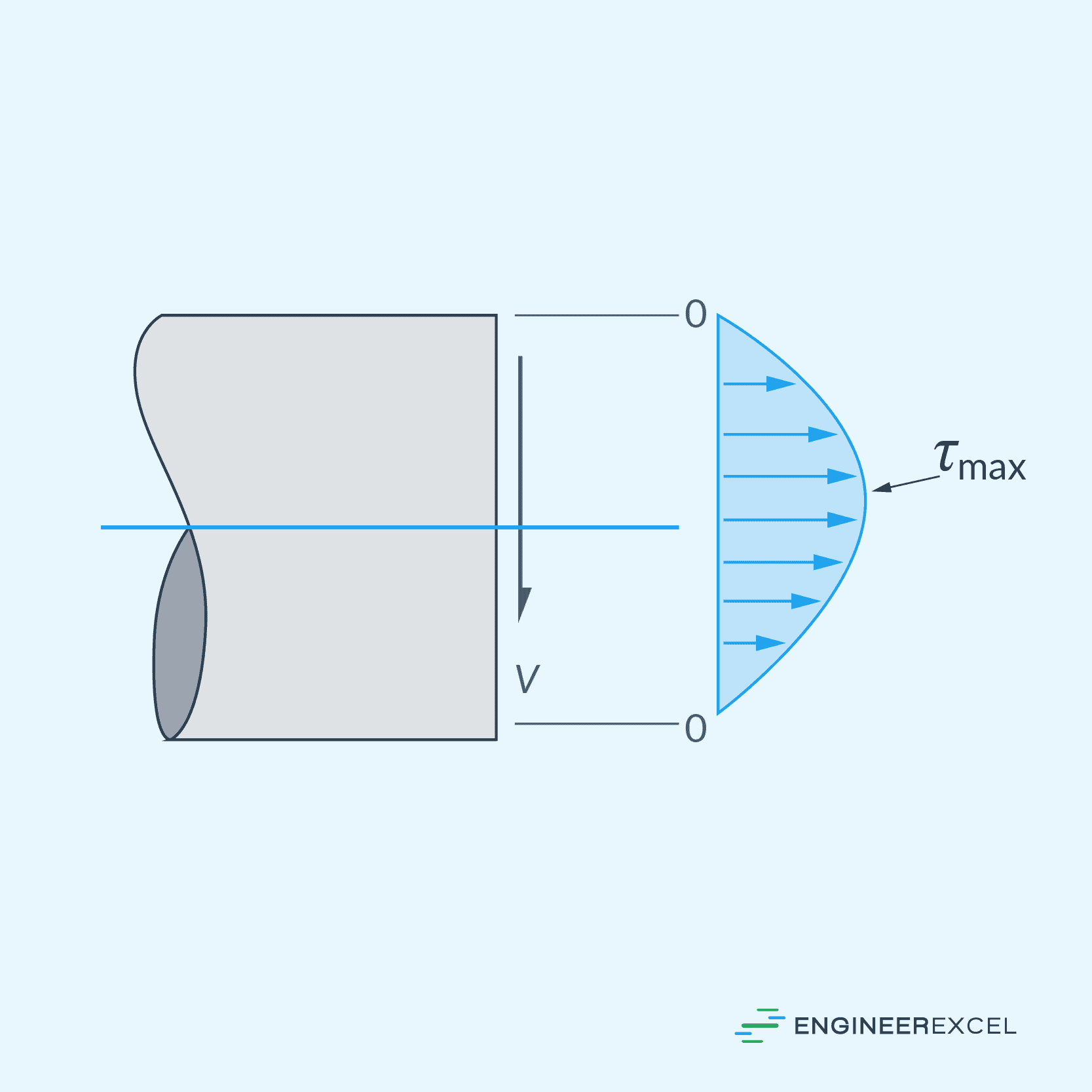
For a solid circular cross-section, the maximum vertical shearing stress can be calculated using the formula:
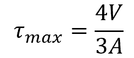
Where:
- τmax = maximum vertical shearing stress [Pa]
- V = vertical shearing force [N]
- A = area of the cross-section [m2]
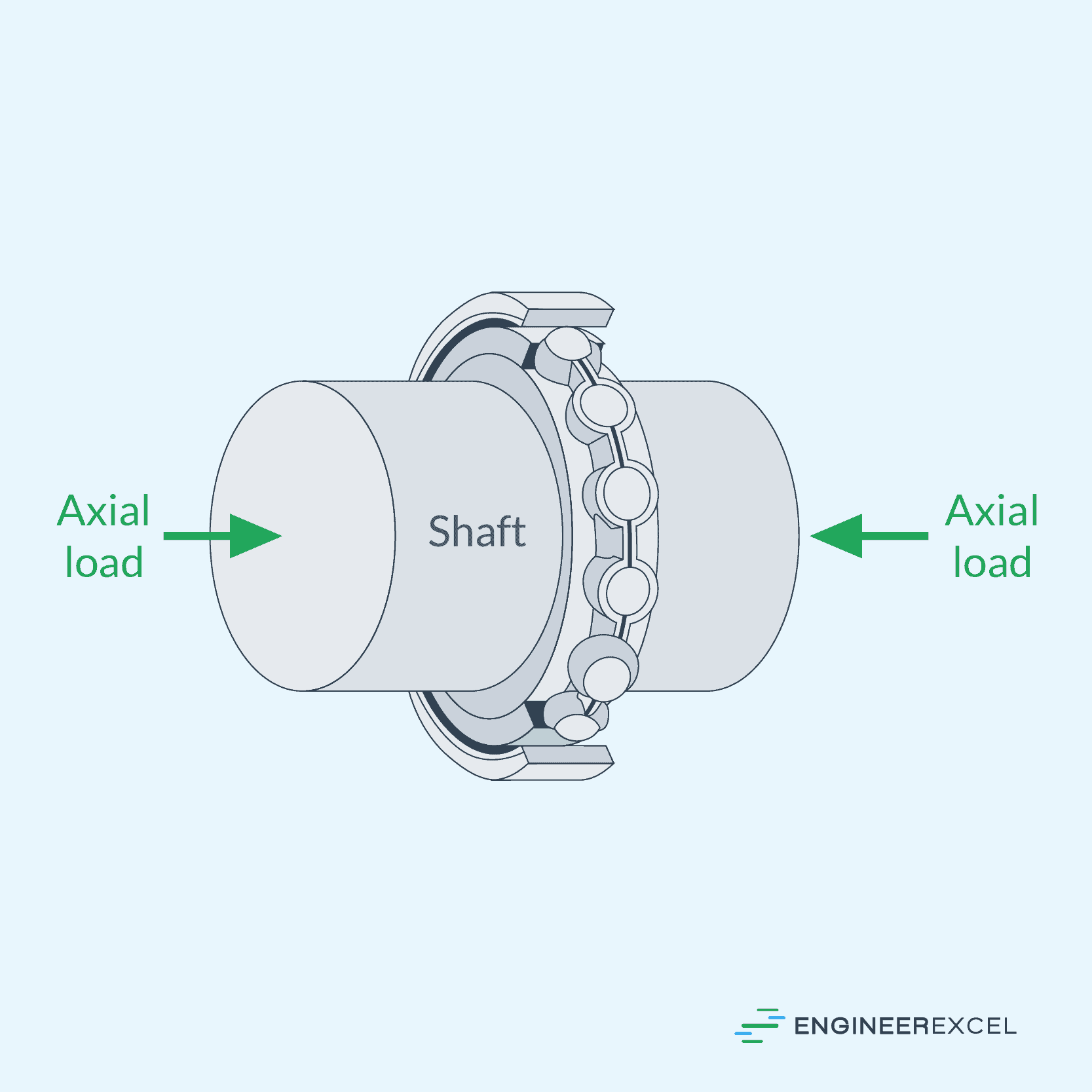
Axial Stress
Axial Stress occurs when a force acts along the axis of the shaft. This force can be either tensile, resulting in elongation of the shaft, or compressive, causing the shaft to shorten.
Axial stress can be calculated using the formula:
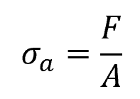
Where:
- σa = axial stress [Pa]
- F = axial load [N]
Stress Concentrations in Shafts
Stress concentrations in shafts are localized areas of higher stress within a shaft or cylindrical structure, which can significantly affect the structural integrity of the shaft. They are normally quantified using stress concentration factors, which are dimensionless parameters used to measure how much the local stress is amplified compared to the nominal or applied stress.
Here are some common causes of stress concentrations in shafts:
Keyways and Splines
Keyways and splines are common features in shafts that transmit torque from one component to another, such as gears or pulleys. These features can create stress concentrations due to the change in geometry and material interruption.
Shaft Shoulders
Shaft shoulders refer to abrupt changes in the shaft diameter, which can create stress concentrations at the interface. When the shaft is subjected to axial or torsional loads, these stress concentrations can lead to localized material failure. The stress concentration factor at a shaft shoulder depends on the fillet radius and the ratio of the two shaft diameters.
To minimize stress concentration in shaft shoulders, it’s crucial to utilize a properly sized fillet radius and avoid sharp corners. Increasing the fillet radius and optimizing the diameter transition can result in a more evenly distributed stress along the shaft.
Shaft Fittings
Shaft fittings, such as bearings and collars, can also induce stress concentrations due to their interference fit with the shaft. The stress concentration at the interface depends on factors like the fit type, tightness, and material properties. Proper mounting and alignment methods are essential in preventing stress concentrations and subsequent material failure.
Shaft Stress Analysis Methods
In the analysis of stresses in a shaft, various methods can be employed. This section will explore three widely-used methods: the Analytical Method, the Numerical Analysis, and Experimental Methods. The choice of method depends on the requirements of the specific problem.
Analytical Method
The analytical method involves the use of known mathematical models and equations to represent the stresses within a shaft. This method is typically effective for simple shaft geometries and loading conditions.
The main advantage of the analytical method is its simplicity and quickness in computing the stress values when given the required parameters. However, the analytical method may become complex and challenging to implement for more intricate geometries and loading conditions.
Numerical Analysis
Numerical analysis uses computational tools to approximate the stress distribution in a shaft, such as the Finite Element Method (FEM). In FEM, the shaft is divided into smaller, interconnected elements, and the governing equations are discretized and solved for each element. This results in a highly detailed stress distribution map across the entire shaft.
The primary advantage of numerical analysis is its ability to handle complex geometries, material properties, and loading conditions. However, the accuracy of the numerical solution depends on several factors such as the choice of mesh, equations used, and solver settings. Additionally, numerical methods can be more time-consuming and computationally demanding compared to analytical methods.
Experimental Methods
Experimental methods provide a hands-on approach to measuring stresses in a shaft. Techniques such as strain gauge measurements, X-ray diffraction, and photoelasticity can be used to directly measure stress values on the shaft. These methods often involve physical testing of the shaft under real or simulated loading conditions, giving a clear picture of the actual stress distribution within the material.
While experimental methods can provide accurate stress data, they may be limited by factors such as cost, equipment availability, and complexity of the test setup. Further, these methods can require significant time and effort compared to analytical or numerical methods.