
Stress concentration refers to the localized increase in material stress that occurs around discontinuities in an object’s geometry. In stepped shafts, stress concentration often occurs at the transition points between different diameters.
Understanding Stress Concentration in Stepped Shafts
Stress concentration is a phenomenon where stress increases around discontinuities in the geometry of an object, such as changes in shape, holes, or notches. The effect is prominent in regions where there is a sudden change in shape or cross-sectional area, leading to localized stress increases.
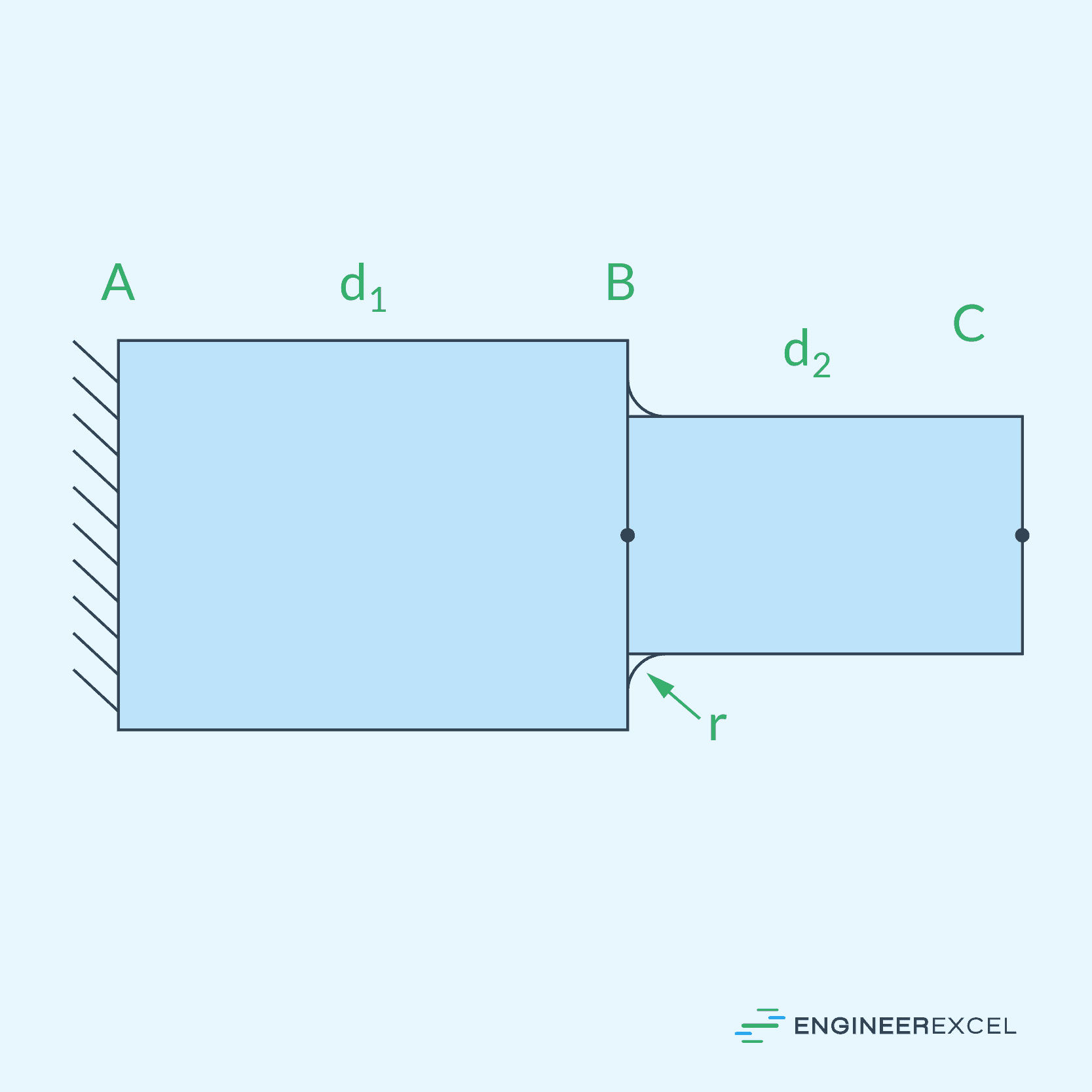
In the context of stepped shafts, stress concentration often occurs at the transition points between various diameters. Stepped shafts are cylindrical objects with multiple sections of different diameters, as shown in the diagram below. These sections are connected by transition zones, which are usually designed with fillets, avoiding sharp edges to minimize the impact of stress concentration.

Elevate Your Engineering With Excel
Advance in Excel with engineering-focused training that equips you with the skills to streamline projects and accelerate your career.
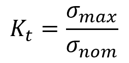
Stress concentration is normally quantified using a dimensionless parameter called the stress concentration factor. It is defined as the ratio of the maximum stress at the location of the step to the nominal or applied stress.
For shafts under normal stress:
Where:
- Kt = stress concentration factor [unitless]
- σmax = maximum normal stress at the location of the step [Pa]
- σnom = nominal normal stress [Pa]
For shafts under shear stress:
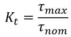
- τmax = maximum shear stress at the location of the step [Pa]
- τnom = nominal shear stress [Pa]
Understanding stress concentration and their distribution is important for ensuring the structural integrity and durability of the shaft, as excessive stress concentrations can lead to fatigue and ultimately result in catastrophic failure.
Factors Affecting Stress Concentration in Stepped Shafts
The stress concentration factor in stepped shafts can be influenced by several factors, including the type of loading, shaft geometry, diameter ratio, and step geometry.
Type of Loading
Shafts can experience different types of loading conditions, such as axial, torsional, or bending loads. The specific loading condition affects how stress is distributed along the shaft and how it is affected by the step. Therefore, different loading conditions can lead to different stress concentration factors for the same stepped shaft geometry.
Shaft Geometry
The shape of the shaft’s cross-section also affects the stress concentration. Shapes with sharp corners tend to increase the stress concentration factor, as stress tends to concentrate at these points. This is why circular or smooth geometries are often preferred in engineering applications.
Diameter Ratio
The diameter ratio in a stepped shaft is the ratio of the larger diameter to the smaller diameter of the shaft. In general, a larger diameter ratio typically results in a higher stress concentration factor. This is because a larger diameter ratio leads to a steeper transition between the different shaft diameters.
Step Geometry
The stress concentration in a stepped shaft is also dependent on the geometrical features at the steps. Sharp corners at the steps can lead to increased stress concentration. To minimize this impact, fillets with large radii are often recommended to provide a smoother transition between the two shaft sections.
The smoothness of a fillet can be quantified using the radius ratio, which is the ratio of the fillet radius to the smaller diameter of the shaft. In general, the larger the radius ratio, the lower the stress concentration factor.
Stress Concentration Factors for Round Shafts
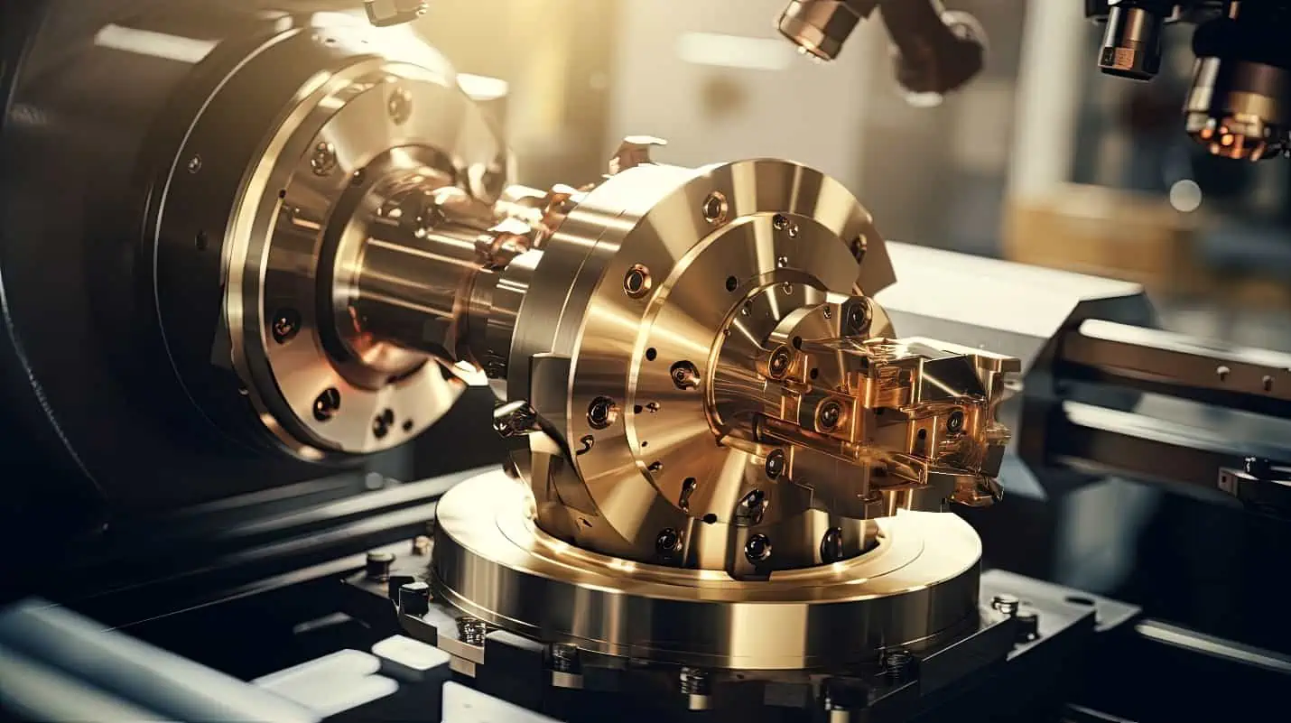
There are several charts and tables available that provide stress concentration factors based on the type of loading, diameter ratio, and radius ratio. For example, the charts for each type of loading for round shafts obtained from Machine Elements in Mechanical Design by R. Mott are shown below.
Tensile Load Stress Concentration Factors
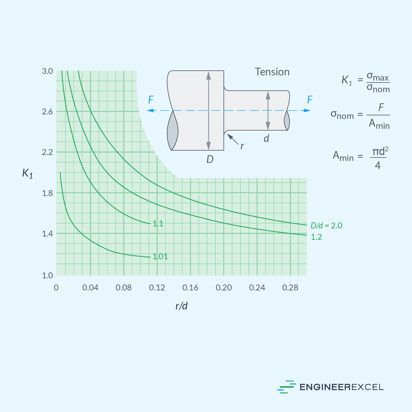
Bending Load Stress Concentration Factors
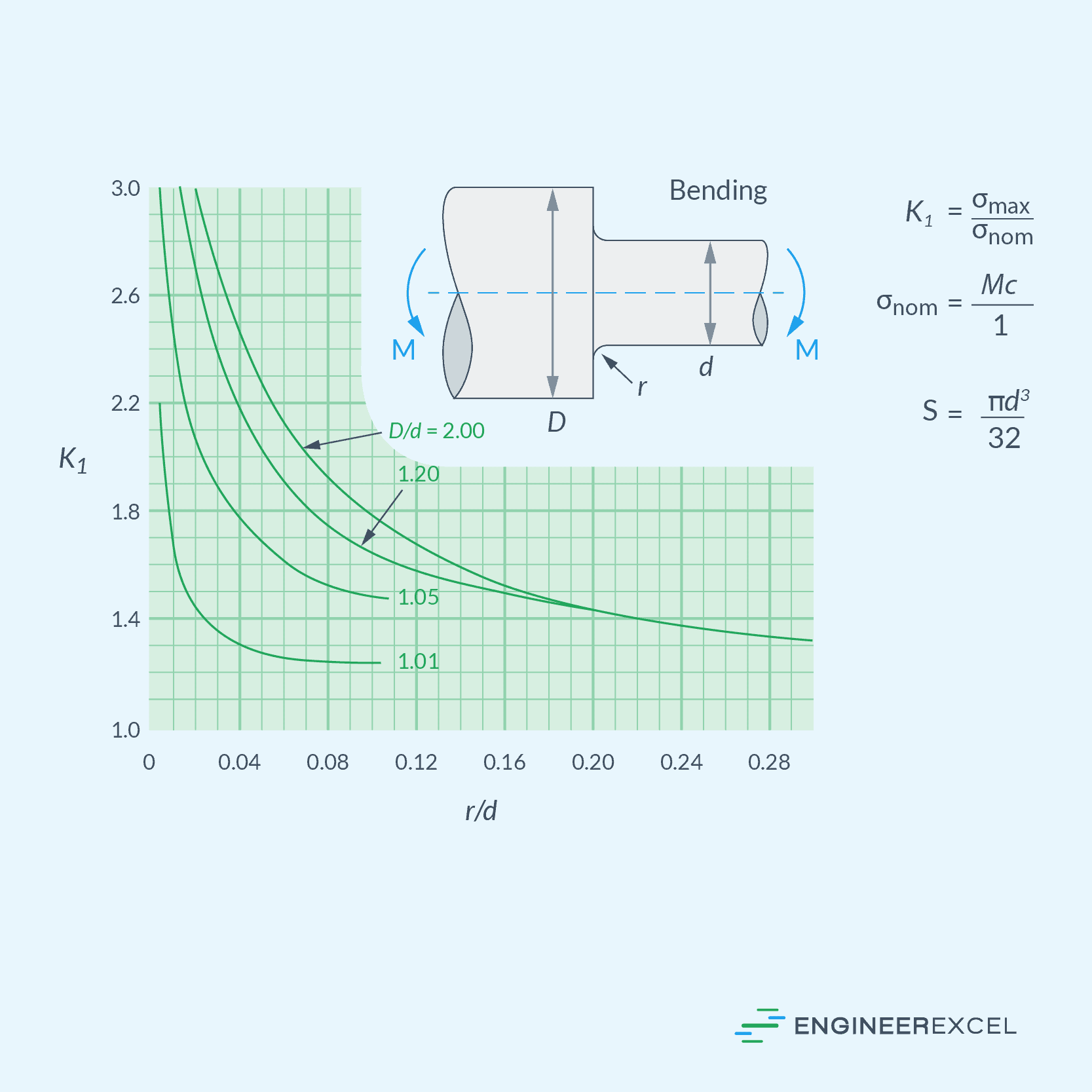
Torsional Load Stress Concentration Factors
It is important to remember that these factors are only applicable to static loading conditions and may not accurately represent the stress concentration for dynamic loading or cases with significant material property variation.
Example Problem
Problem: A stepped shaft with diameters d = 40 mm and D = 50 mm is loaded by torque T = 1100 N-m. Determine the maximum shear stress at the shaft step if the fillet radius is 8 mm.
Solution:
First, calculate the nominal torsional shear stress at the fillet using the torsion formula:
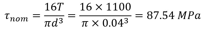
Knowing that:
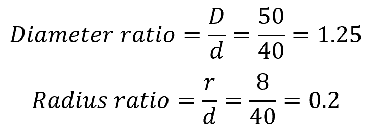
Based on the chart above, the torsional stress concentration factor is approximately equal to 1.2. Then, the maximum torsional shear stress at the fillet can be calculated as follows:

The maximum torsional shear stress is 105.05 MPa.