
Shear flow is a measure of the shear force per unit length along the axis of a beam. It is an important concept in solid mechanics that explains how shear stress is distributed within a structure when it’s subjected to transverse loading.
In this article, we will discuss what shear flow is, how to calculate it, and its applications in analyzing various engineering applications, including built-up beams, thin-walled members under shear, and thin-walled tubes under torsion.
What is Shear Flow
Shear flow is a concept in solid mechanics that explains how shear stress is distributed within a structure when it’s subjected to transverse loading. Transverse loading refers to external forces that act perpendicular to the main axis of the structure, leading to shear stress that runs parallel to the material’s cross-sectional area. This causes one part of the material to slide or deform relative to another part.
In essence, shear flow is a measure of the shear force per unit length along the axis of a beam, measured in Newtons per meter (N/m) or pounds per foot (lb/ft). In a structural component, the shear flow is not necessarily uniform across the cross-section. In general, it varies with the distance from the neutral axis, which is the axis about which the component rotates when subjected to bending.

Elevate Your Engineering With Excel
Advance in Excel with engineering-focused training that equips you with the skills to streamline projects and accelerate your career.
The maximum shear flow always occurs at the neutral axis location, but it does not necessarily mean that the maximum shear stress also occurs at the same location. This is because the thickness of the material may vary at different points.
One of the primary reasons to study shear flow is to determine the shear stress distribution in a beam or plate. Shear stress plays a crucial role in structures, as it has the potential to cause material failure or distortion. Understanding and predicting shear stress throughout the structure helps engineers design safer and more resilient structures.
Shear Flow Calculation
The formula for shear flow (q) is given by:
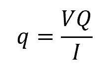
Where:
- q = shear flow [N/m]
- V = shear force acting on the section [N]
- Q = first moment of area of the section with respect to the neutral axis [m3]
- I = moment of inertia of the section about the same axis [m4]
The first step in calculating shear flow is determining the shear force (V) acting on the beam. This can be obtained by analyzing the beam’s loading conditions and creating a shear and moment diagram. Shear force can arise from various sources, such as concentrated loads or distributed loads along the length of the beam.
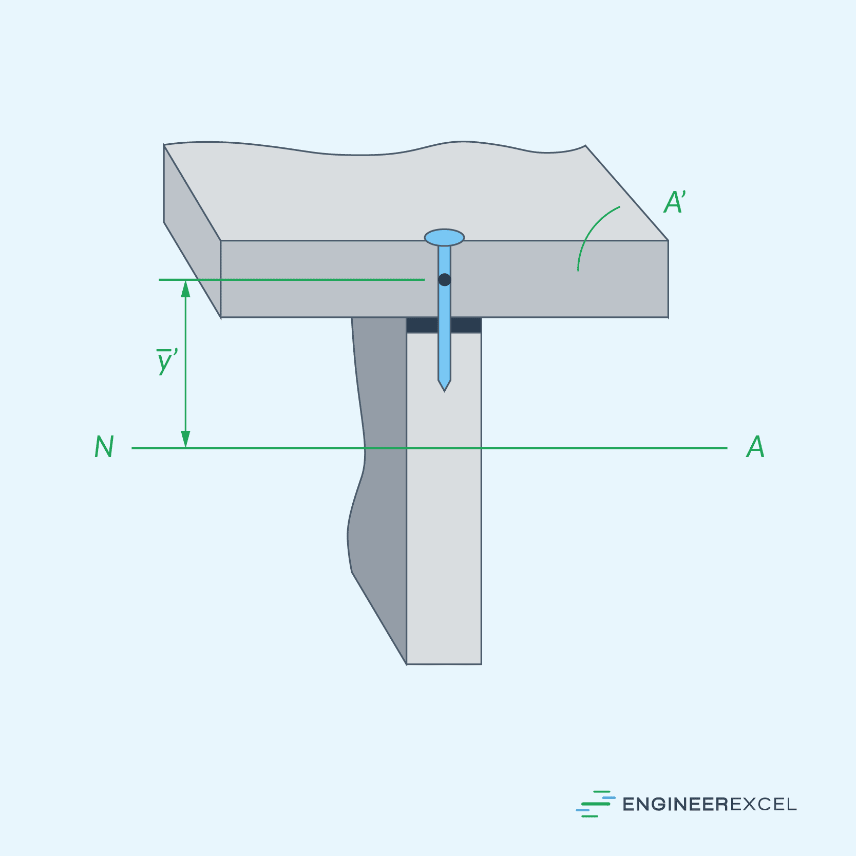
The first moment of area (Q) about the neutral axis can be calculated using the following formula:
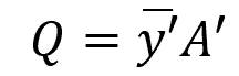
Where:
- A’ = cross-sectional area of the section above (or below) the point of interest [m2]
- y’ = distance of the area’s centroid from the neutral axis [m]
Lastly, the moment of inertia (I) for the beam’s cross-section can be determined from the geometry using the parallel axis theorem or using standard tables for common shapes like rectangular, circular, or I-sections.
Applications of Shear Flow
The concept of shear flow is used to analyze various engineering applications, including built-up beams, thin-walled members under shear, and thin-walled tubed under torsion.
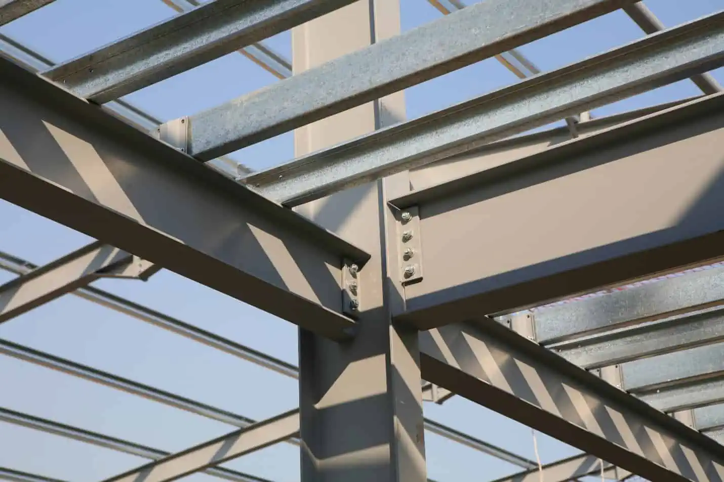
Built-up Beams
In engineering practice, built-up beams are often used to achieve greater resistance to loads. These beams are created by combining several composite parts, such as nails, bolts, welding material, or glue, to keep the component parts from sliding relative to one another.
To design these fasteners or determine their spacing, the shear loading that must be resisted by the fastener is important. This loading is measured per unit length of beam, referred to as shear flow.
Thin-Walled Members Under Shear
The concept of shear flow can also be used to analyze thin-walled members subjected to shear forces. In this case, the shear force should act along an axis of symmetry or the principal centroidal axis of inertia for the cross-section.
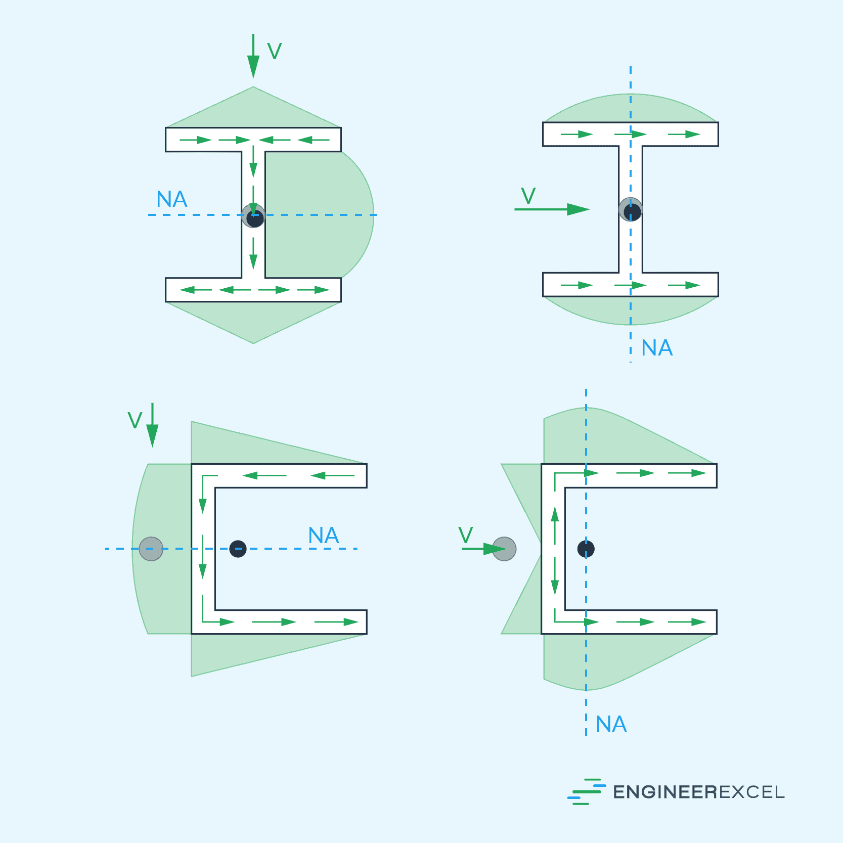
When dealing with thin-walled members, the critical aspect to focus on is the shear flow parallel to the walls. The shear flow exhibits different behavior depending on the orientation of the segments relative to the direction of the shear force.
For segments perpendicular to V, the shear flow varies linearly along them. Conversely, segments that are either inclined or parallel to the direction of the applied shear force demonstrate a parabolic variation in the shear flow. This behavior is illustrated in the diagram below.
Thin-Walled Tubes Under Torsion
In thin-walled tubes under torsion, the shear flow is determined by multiplying the thickness of the tube by the average shear stress.
In this case, the shear flow remains constant across all points of the tube’s cross section. As a result, the highest average shear stress occurs where the thickness of the tube is the smallest.
Both the shear flow and the average shear stress act tangentially to the tube’s wall and contribute to the internal torque in the same direction.