
Featured Bending Resources
[no_toc]
Area Moment of Inertia: A Key Concept in Solid Mechanics
Composite Beam Bending: Analysis and Design Considerations
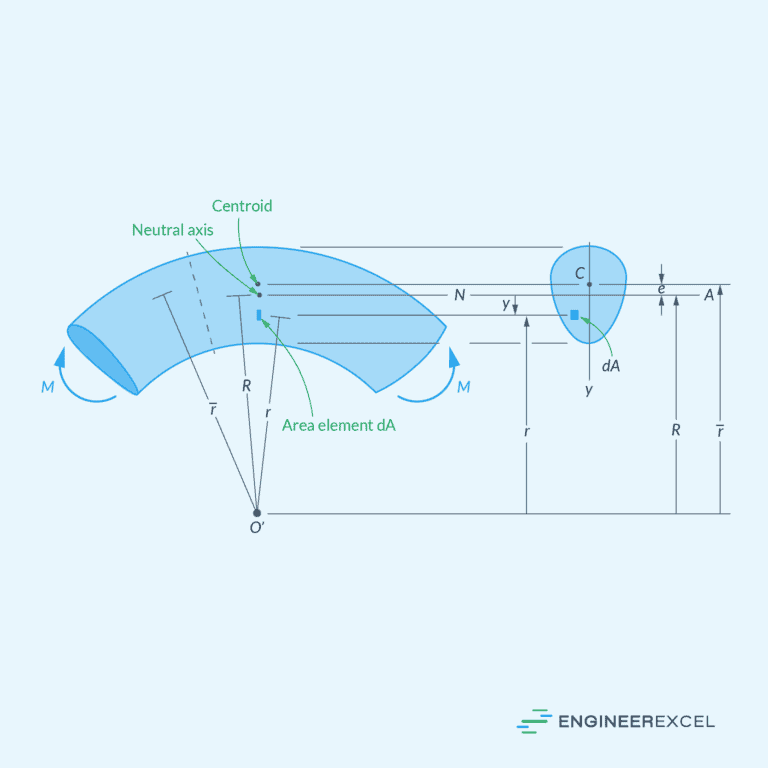
Bending Stress Analysis in Curved Beams: Understanding the Mechanics

Bending Stress Concentration: Key Considerations in Efficient Structural Design
Section Modulus: Calculators and Complete Guide
Neutral Axis Understanding its Role in Solid Mechanics
Bending Stress Formula for Beam Analysis
Bending Stress in Beams Undergoing Plastic Deformation
Bending refers to the deformation of a structural element due to the application of external forces, causing it to curve or flex.
In this article, we will discuss the fundamentals of bending, including bending moment, bending stress distribution, area moment of inertia, section modulus, bending in composite beams, bending stress concentrations, and plastic deformation in bending.
Fundamentals of Bending
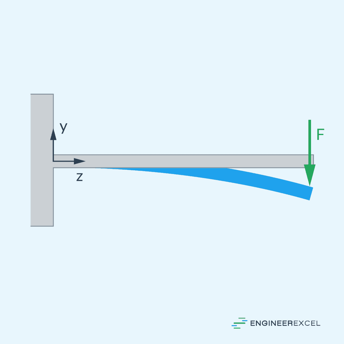
When a beam is subjected to a load perpendicular to its longitudinal axis, the resulting deformation is called bending. The internal resistance to this deformation is generated by the beam’s material, producing stress and strain distributions within the beam’s cross-section.

Elevate Your Engineering With Excel
Advance in Excel with engineering-focused training that equips you with the skills to streamline projects and accelerate your career.
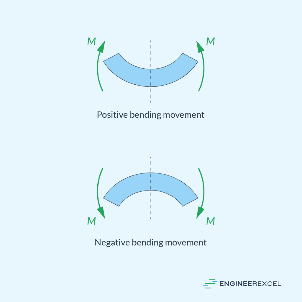
Bending Moment
As a result, the beam experiences internal forces called the bending moment, which can be calculated using the following equation:
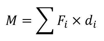
Where:
- M = bending moment [N-m]
- Fi = each individual force acting on the beam [N]
- di = perpendicular distance from the force to the point of interest in the beam [m]
The bending moment varies along the length of the beam. Its distribution is influenced by the type of load and support conditions on the beam.
Bending Stress Formula
If the bending moment is known at a point, the stress due to bending in the beam’s cross-section can be calculated using the flexure formula:
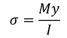
Where:
- σ = bending stress [Pa]
- y = distance from the neutral axis to the point at which the stress is being calculated [m]
- I = moment of inertia of the cross-section [m4]
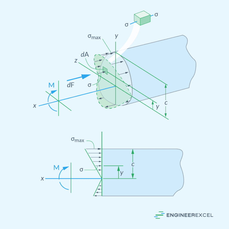
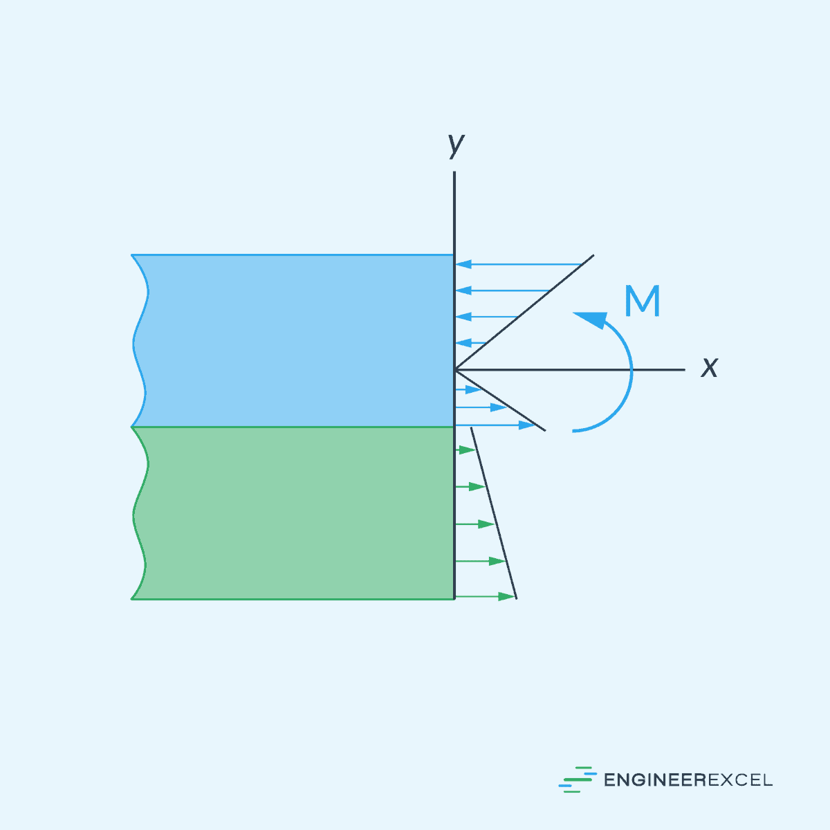
As shown in the diagram below, the stress at a point depends on its distance from the neutral axis.
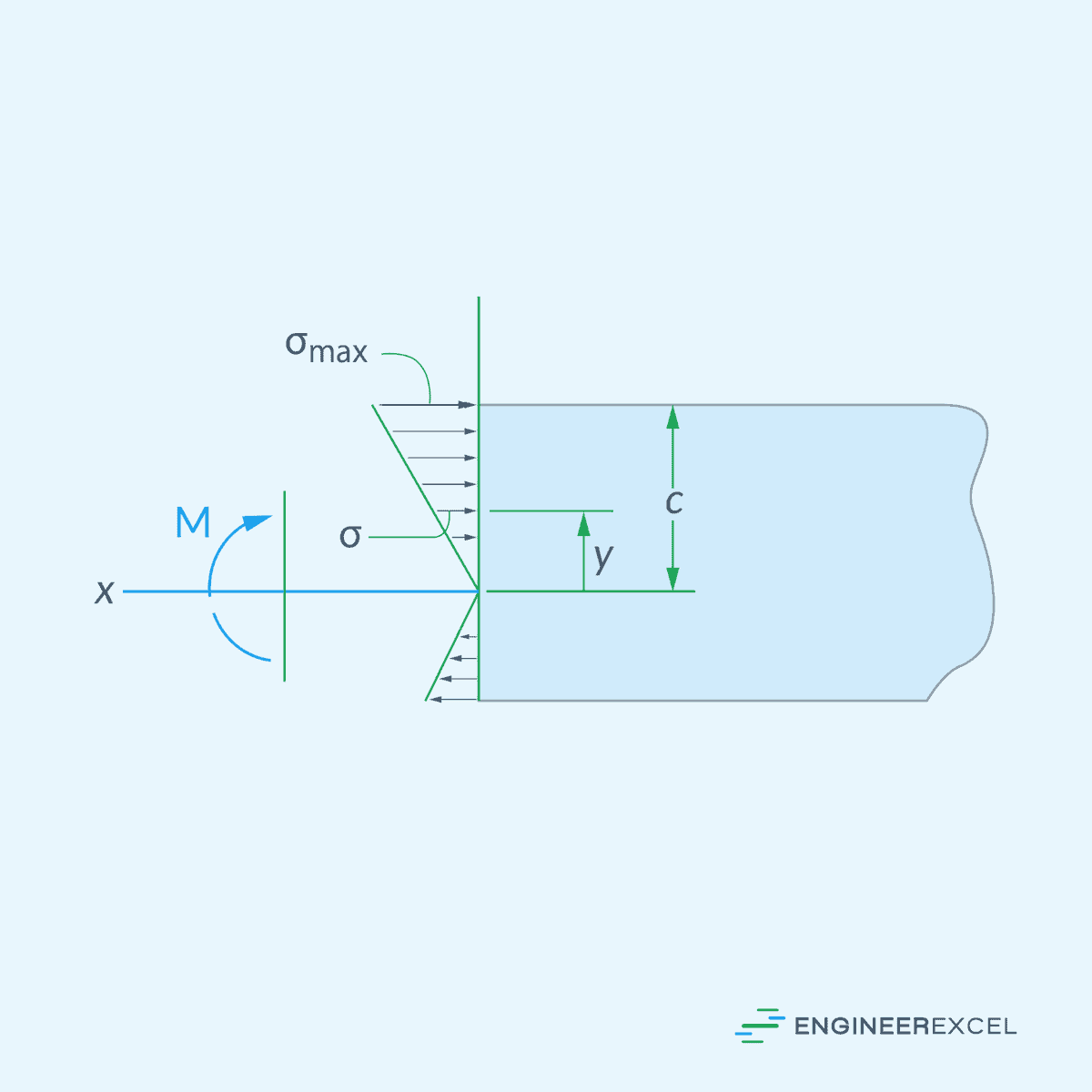
The neutral axis is a line or plane in the beam’s cross-section where the stresses transition from compression to tension. At this location, there is no elongation or compression, and as a result, the axial stress is zero. From the neutral axis, the normal stress increases linearly towards the extreme fibers of the beam.
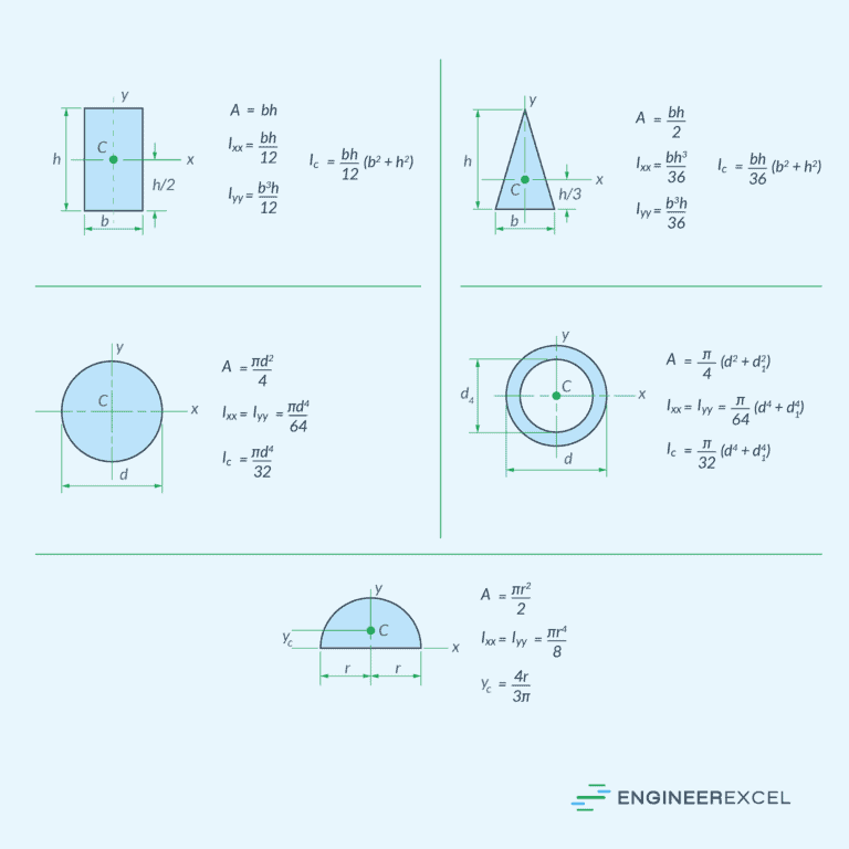
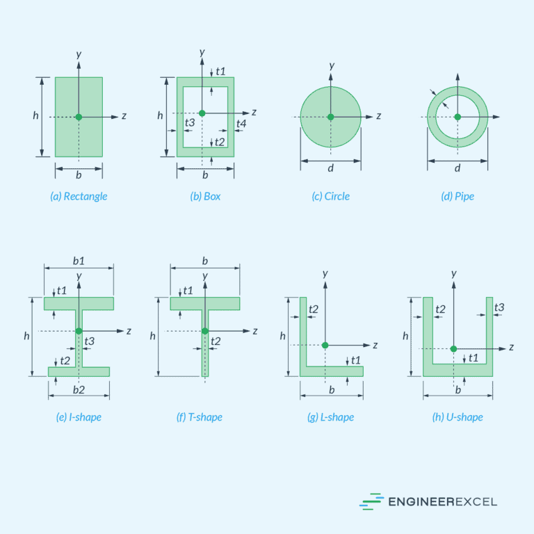
Area Moment of Inertia
One of the parameters important in bending analysis is the area moment of inertia (I). Also known as the second moment of area, it quantifies a structural shape’s resistance to bending and is calculated by summing the products of individual area elements squared and their respective distances from a specified axis.
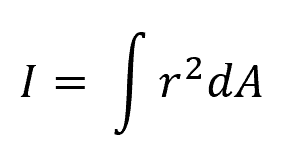
Where:
- r = distance of each area element from the reference axis [m or in]
- dA = infinitesimally small area element [m2 or in2]
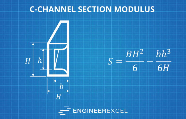
Section Modulus
Another parameter that is commonly used in bending analysis is the section modulus, which can be calculated as:
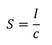
Where:
- S = section modulus [m3]
- c = distance from the neutral axis to the extreme fiber of the cross-section [m]
Derived from the area moment of inertia, it represents a cross-sectional shape’s resistance to bending. The greater the section modulus, the higher the bending capacity of a cross-section.
When designing beams, given a maximum bending moment and allowable bending stress of a beam material, the required section modulus can be calculated using the following formula:
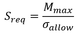
Where:
- Sreq = required section modulus [m3]
- Mmax = maximum bending moment along the beam [N-m]
- σallow = allowable bending stress for the beam material [Pa]
Once the required section modulus is calculated, the possible dimensions and geometry of the beam can be determined.
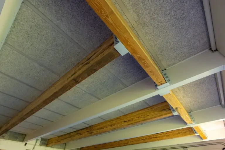
Bending in Composite Beams
The bending concepts discussed above generally only apply to beams made of one material. For composite beams made of different materials, bending analysis is different.
Composite beams are crafted by integrating various materials or components to create a unified, resilient load-bearing structure. By combining different materials, they are able to effectively resist bending and shear forces, leading to increased load-carrying capacity and reduced deflection.
To understand how bending stress behaves in a composite beam, consider the diagram of a composite beam made of two materials with different stiffness levels, shown below.
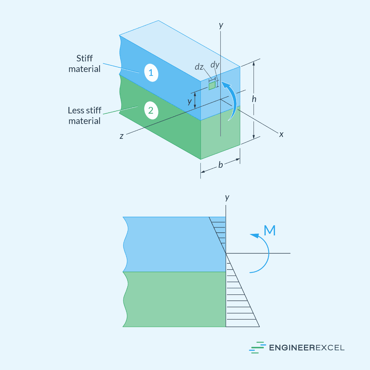
If a bending moment is applied to this beam, the normal strain will vary linearly from zero at the neutral axis to a maximum at the outermost fibers of the beam. However, since the two materials have different stiffness levels, the corresponding stress for each material will be different. Hence, there will be a sudden jump in stress at the juncture of the two materials, as shown in the diagram below.
Bending analysis of composite beams is done using the Transformed Section Method. This method involves transforming the composite section into an equivalent section with uniform material properties, providing a more straightforward approach to analyze the overall behavior of the composite beam.
Stress Concentration in Bending
Stress concentration in bending refers to the local increase in stress that occurs in an object due to a change in geometry, such as notches, holes, or irregular shapes. When a beam is subjected to bending forces, high-stress gradients may develop near these geometrical discontinuities, leading to the formation of stress concentrations. The presence of stress concentrations can significantly impact the overall performance and structural integrity of a beam, making it essential to consider these factors during the design process.
In order to account for stress concentrations in bending, engineers typically use stress concentration factors (Kt) to calculate the local bending stress. The formula to determine the bending stress (σ) then becomes:
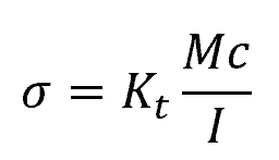
Where:
- Kt = bending stress concentration factor [unitless]
The stress concentration factor depends on the geometry of the discontinuity and can be obtained from engineering handbooks or experimental data.
Plastic Deformation in Bending
Most discussions about bending involve elastic deformation, where materials deform and return to their original shape when the applied stress is removed. In this region, Hooke’s Law is obeyed, represented by the linear relationship between stress and strain.
However, when the applied moment causes the beam deform past the elastic limit, the conventional bending equations become inapplicable. In the plastic deformation region, materials continue to deform even after the removal of the applied stress, which results in permanent deformation. In this case, plastic analysis is required to determine the stress distribution.
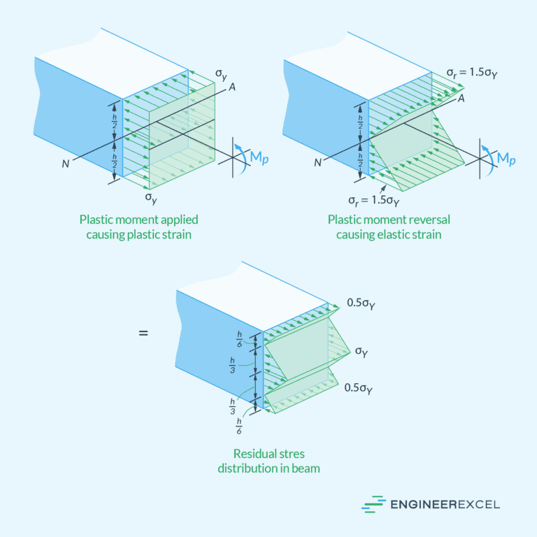
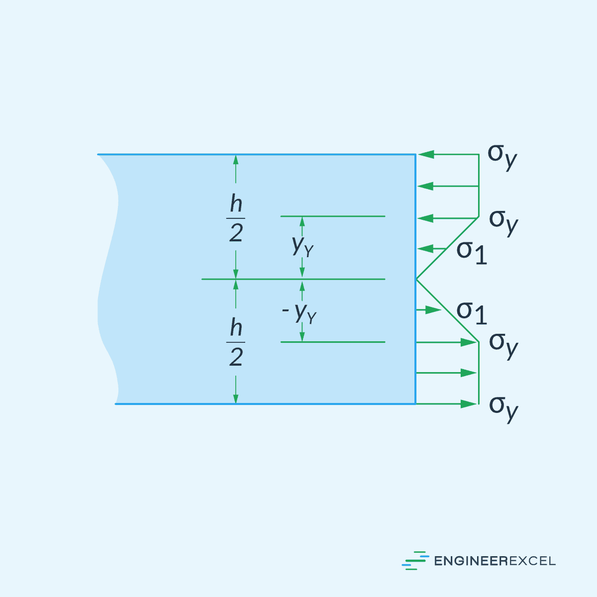
There are two possible scenarios that could happen. First is, if the applied moment is not sufficient to plastically deform the whole cross-section, it would produce two separate zones of plastic yielding with uniform stress at the top and bottom sections, and an elastic section at the center, as shown in the diagram below.
The second scenario is, if the applied moment causes the whole cross-section to plastically deform, the elastic stress distribution at the center disappears and the stress distribution becomes constant over the whole section.
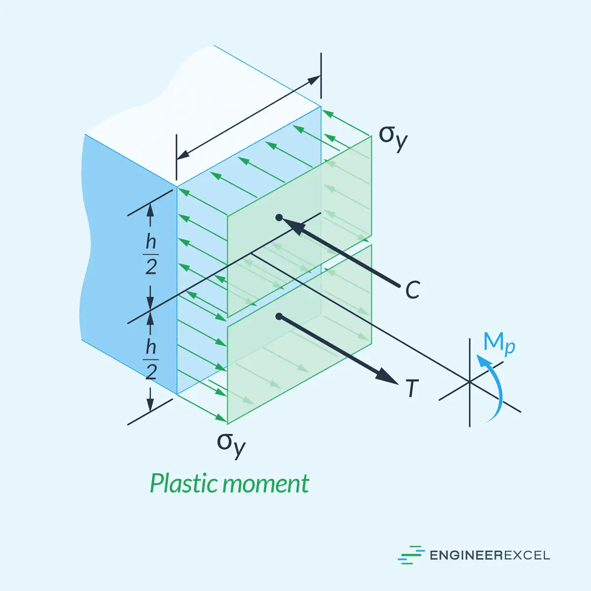
The magnitude of the moment at which the whole cross-section starts to deform plastically is called the plastic moment, which can be calculated for rectangular beams as follows:
Where:
- MY = minimum moment at which plastic deformation starts [N-m]
- MP = plastic moment [N-m]