
Composite beams are structures made by combining different materials to create a stronger and more efficient beam. Compared to beams made of a single homogeneous material, analyzing the bending behavior of composite beams is more complex.

In this article, we will explain how bending stress behaves in composite beams and how to calculate it using the Transformed Section Method.
What are Composite Beams
Composite beams are beams consisting of a combination of materials or components that work together to create a single, more robust and efficient load-bearing member. They are widely used in construction and engineering to support heavy loads over long spans.
A typical composite beam comprises a concrete slab as the upper element and a steel or composite material (like fiberglass-reinforced polymer) as the lower element. The concrete slab provides a durable and smooth surface for the structure, while the steel or composite material delivers the necessary strength and stiffness.

Elevate Your Engineering With Excel
Advance in Excel with engineering-focused training that equips you with the skills to streamline projects and accelerate your career.
The key concept underlying composite beams is the cooperative interaction between the concrete slab and the steel or composite section. When external loads are applied to the composite beam, these materials collaborate to resist bending and shear forces effectively. The concrete primarily handles the compressive forces, while the steel or composite section takes care of the tensile forces.
This synergy results in various advantages for composite beams, such as increased load-carrying capacity, reduced deflection, and cost-effective designs. Composite beams are versatile and are commonly used in a variety of structures, including bridges, commercial buildings, industrial facilities, and residential construction.
Composite Beam Bending Explained
To understand how bending stress behaves in a composite beam, consider a composite beam made of two materials, shown below. Material 1 is made of stiff material, while material 2 is made of less stiff material.
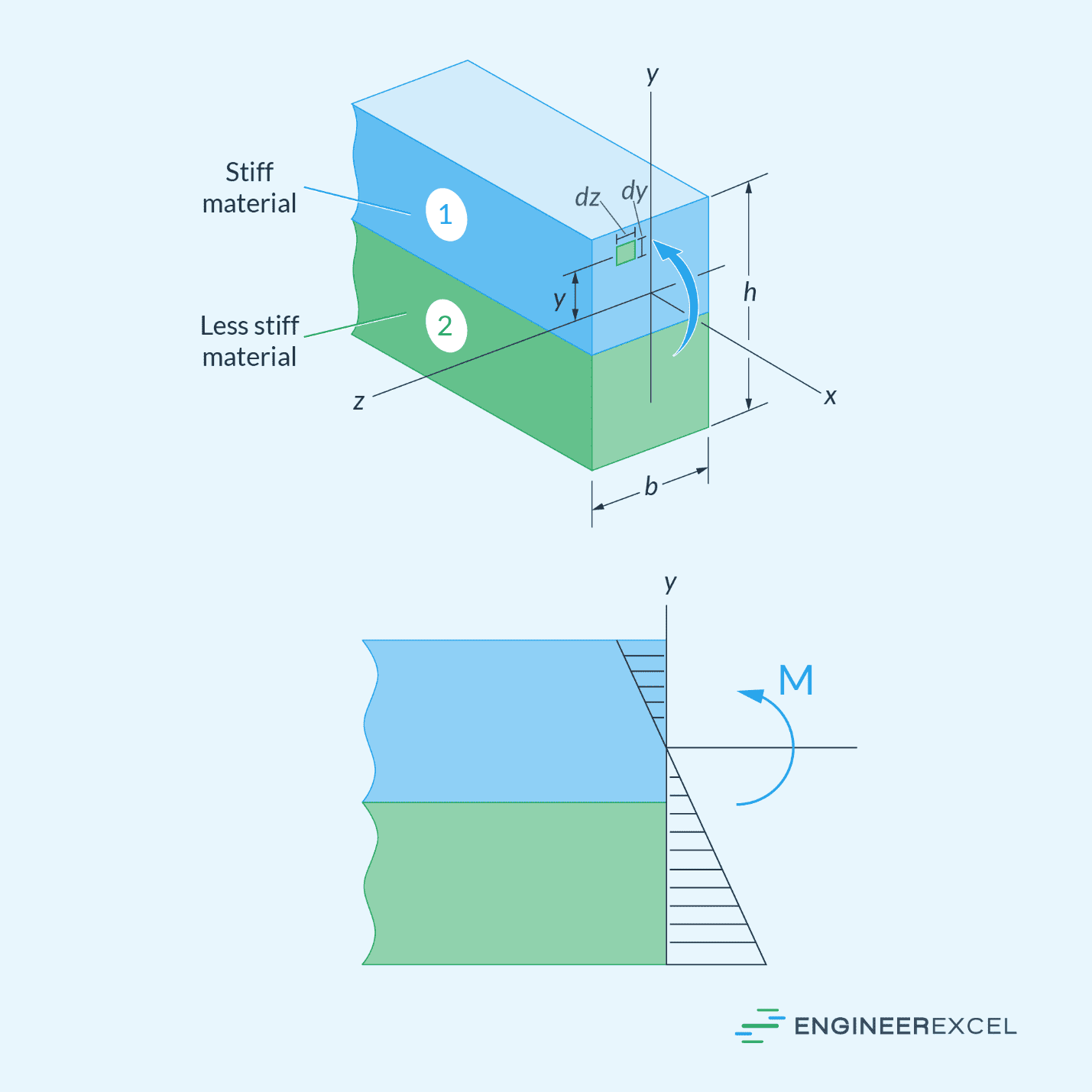
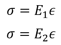
If a bending moment is applied to this beam, assuming the total cross-sectional area remains plane after bending, the normal strain will vary linearly from zero at the neutral axis to a maximum at the outermost fibers of the beam. If the materials are linear elastic, then the normal stresses at any point in material 1 and material 2 can be calculated using the following formulas, respectively:
Where:
- ε = normal strain due to bending [unitless]
- E1 = Young’s modulus of the stiff material [Pa]
- E2 = Young’s modulus of the less stiff material [Pa]
Knowing that material 1 is stiffer than material 2, the stress distribution will look like the figure shown below:
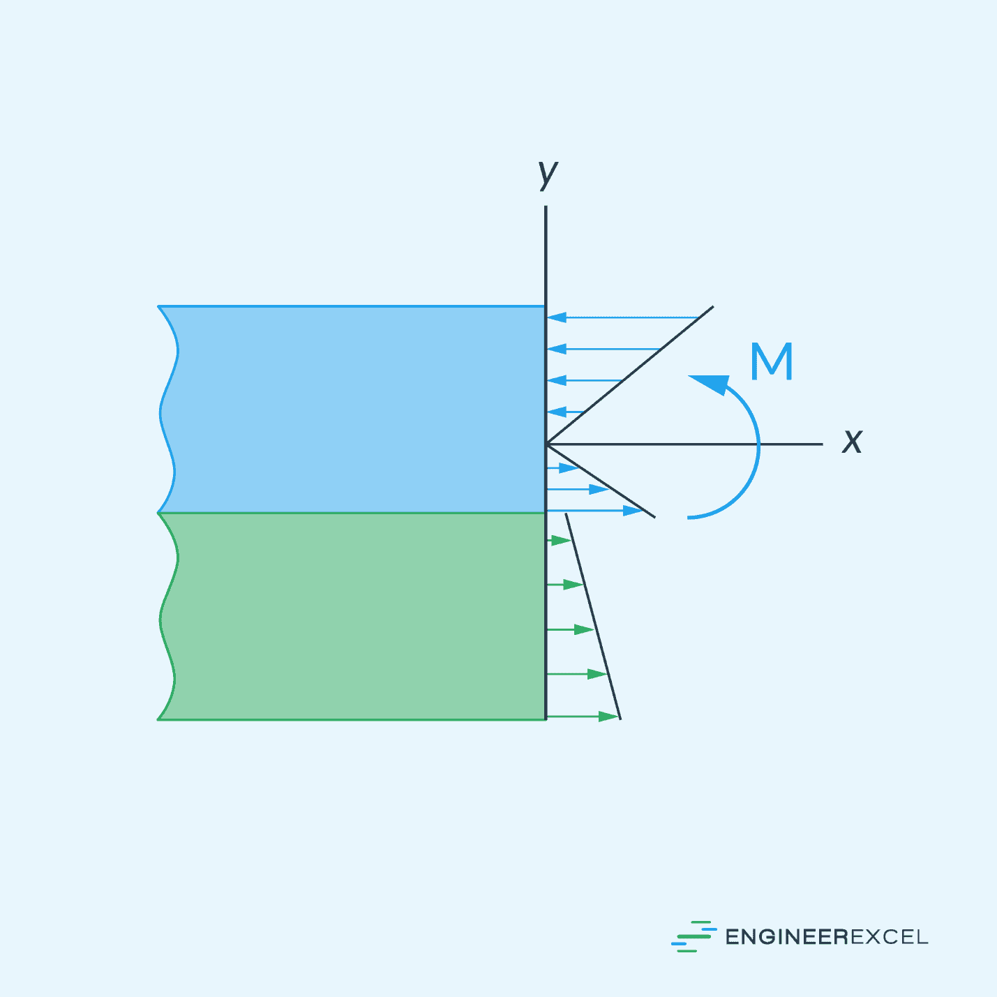
Notice the sudden jump in stress magnitude that occurs at the juncture of the two materials. Here the strain is the same, but since the modulus of elasticity for the materials suddenly changes, so does the stress.
Composite Beam Bending Calculation
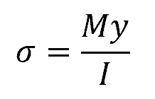
Typically, the flexure formula can be used to determine the normal stress distribution caused by bending in homogeneous beams. This formula is expressed as:
Where:
- σ = normal stress due to bending [Pa]
- M = applied bending moment [N-m]
- y = distance from the neutral axis to the point at which the stress is being calculated [m]
- I = moment of inertia [m4]
However, for composite beams, this formula cannot be used directly to determine the normal stress because composite beams are not homogeneous. Instead, a method called the Transformed Section Method can be used to determine the location of the neutral axis and the maximum stress. This method transforms the composite beam into one made of a single material.
For instance, if the example composite beam above is assumed to be entirely composed of the less stiff material 2, then the upper portion of the beam must be widened to carry a load equivalent to that carried by the stiffer material 1. The cross-section will appear as shown in the figure below.
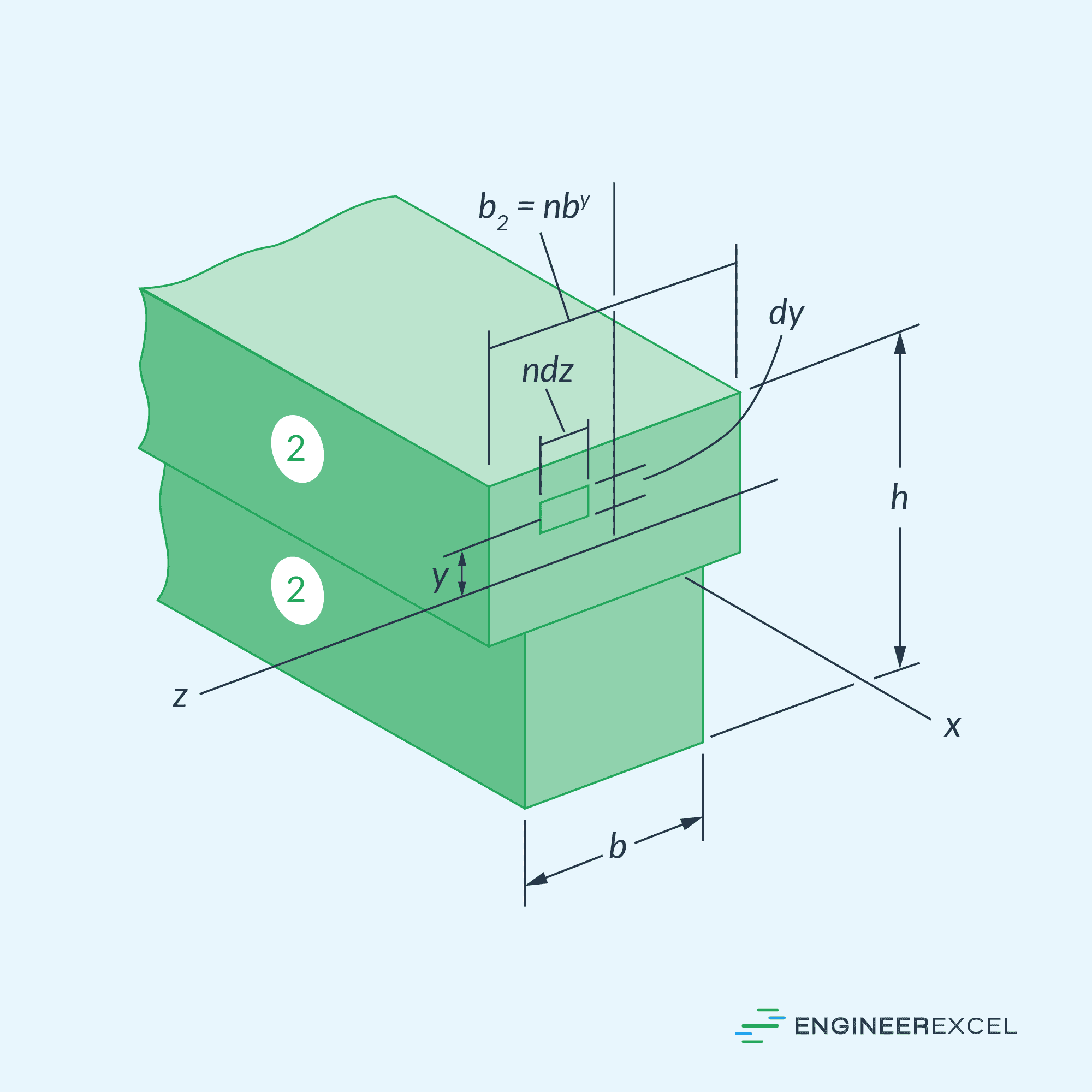
Assuming the height h of the beam remains the same, the necessary width for the enlarged area can be determined using the formula:
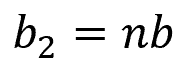
Where:
- b2 = width of the transformed section [m]
- b = width of the original section [m]
- n = transformation factor [unitless]
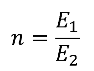
The dimensionless transformation factor is simply the ratio of the materials’ moduli of elasticity, such that:
After transforming the beam, the neutral axis and moment of inertia for the transformed area can be determined. Then, the flexure formula can be applied in the usual manner to determine the stress at each point on the transformed beam. The normal stress distribution over the transformed beam will be linear, as shown in the diagram below.
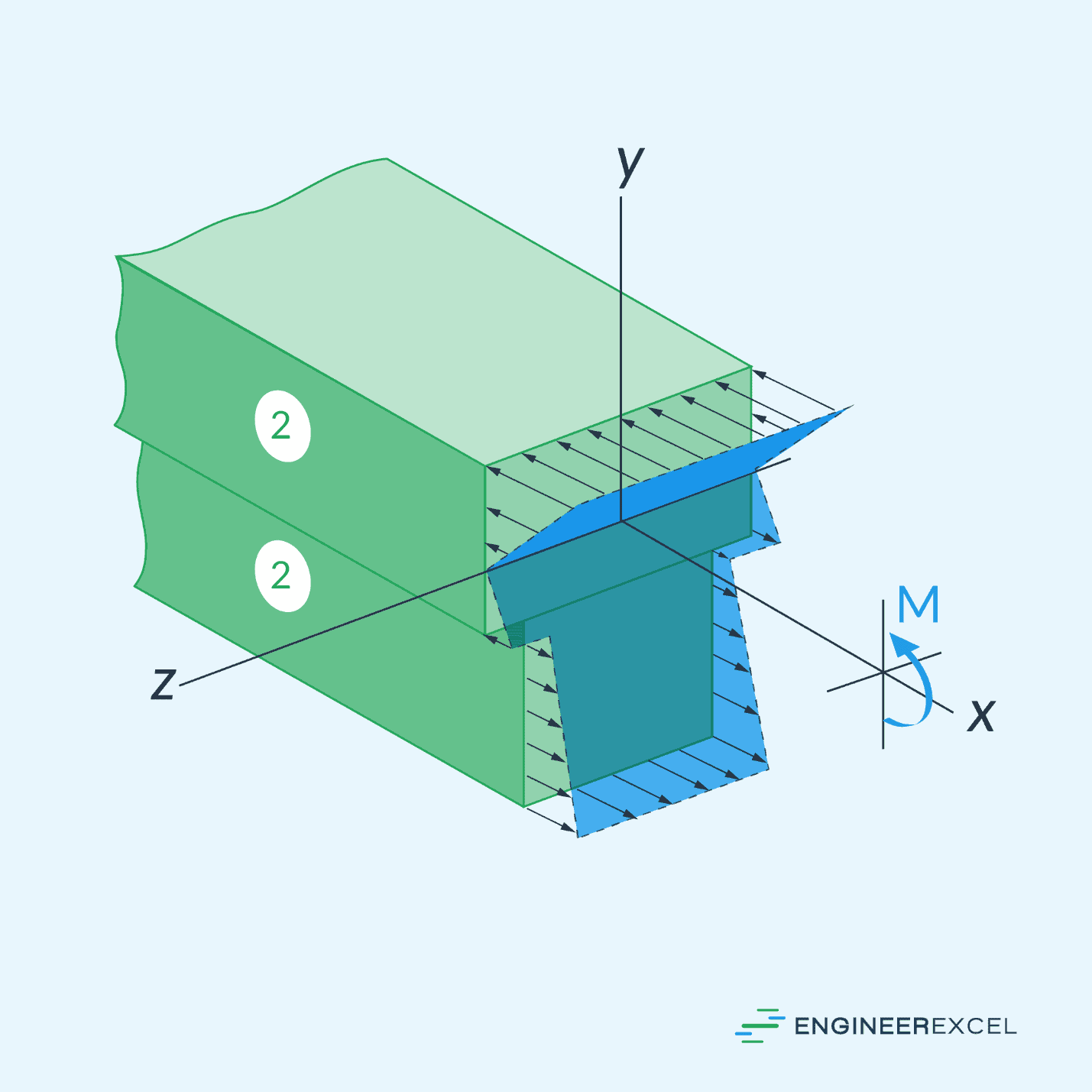
However, to obtain the actual stress on the original material of the beam, the stress found on the transformed section needs to be multiplied by the transformation factor.