
The neutral axis is the axis where the bending stress and strain are zero in a cross-sectional plane of a beam. Understanding this concept is crucial for determining stress and strain distribution and designing safe structures.

In this article, we will explain the neutral axis concept and how to determine its position and orientation for various cross-sectional geometries and loading conditions.
Understanding the Concept of Neutral Axis
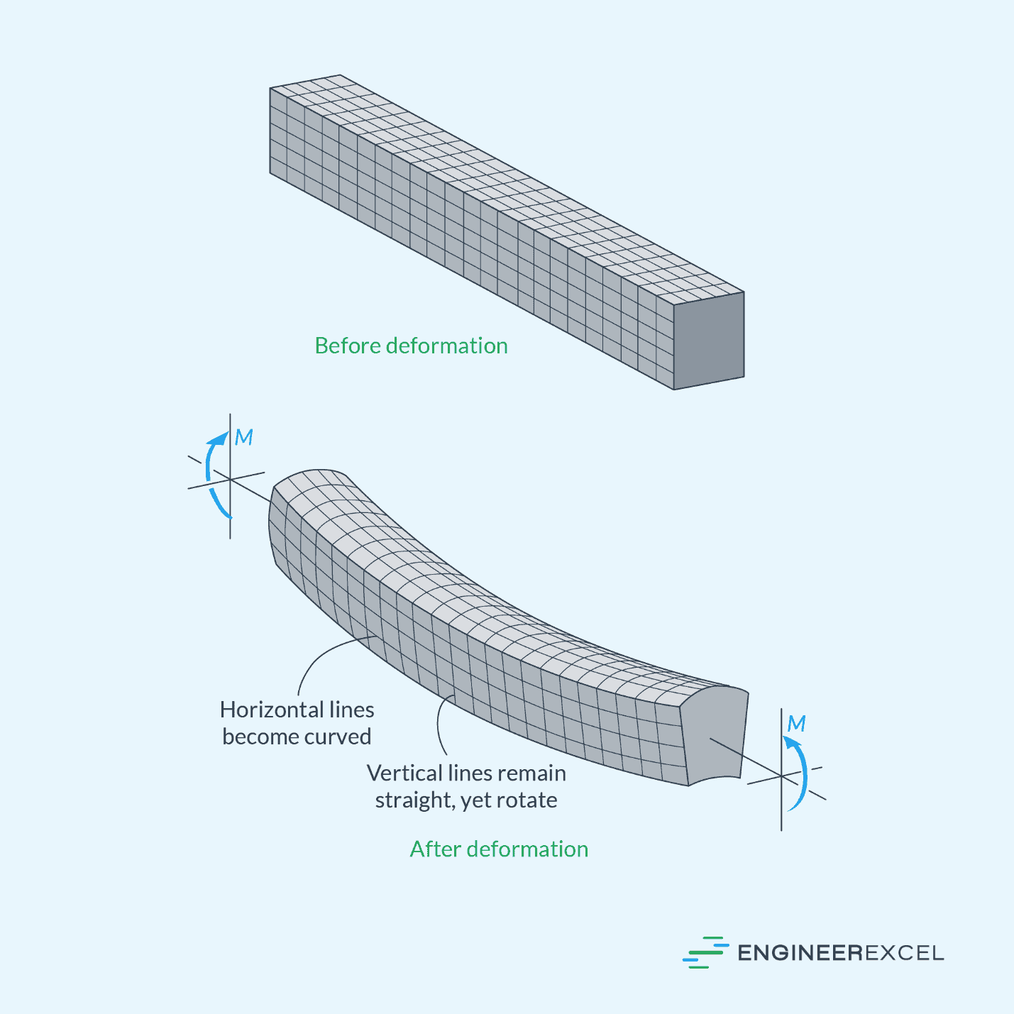
When a beam is subjected to a bending moment, it causes the beam’s longitudinal fibers to curve while the transverse cross-sections remain plane and perpendicular to the longitudinal axis. As a result, the material at the bottom of the beam stretches (in tension) while the material at the top compresses, as shown in the diagram below.

Elevate Your Engineering With Excel
Advance in Excel with engineering-focused training that equips you with the skills to streamline projects and accelerate your career.
In between these tensile and compressive sections, there exists a neutral surface where the longitudinal fibers do not change in length. This is where the neutral axis lies.
The neutral axis of a beam’s cross-section is defined as an axis that lies along both the cross-sectional plane and the neutral surface, along which the bending stress and strain are zero. This means that in the vicinity of this axis, the structural member neither contracts nor expands, remaining essentially “neutral” to the effects of bending.
For a linear-elastic material, like steel, the normal stress and strain will vary linearly from zero at the neutral axis to a maximum value at the outermost fiber, as illustrated in the diagram below.
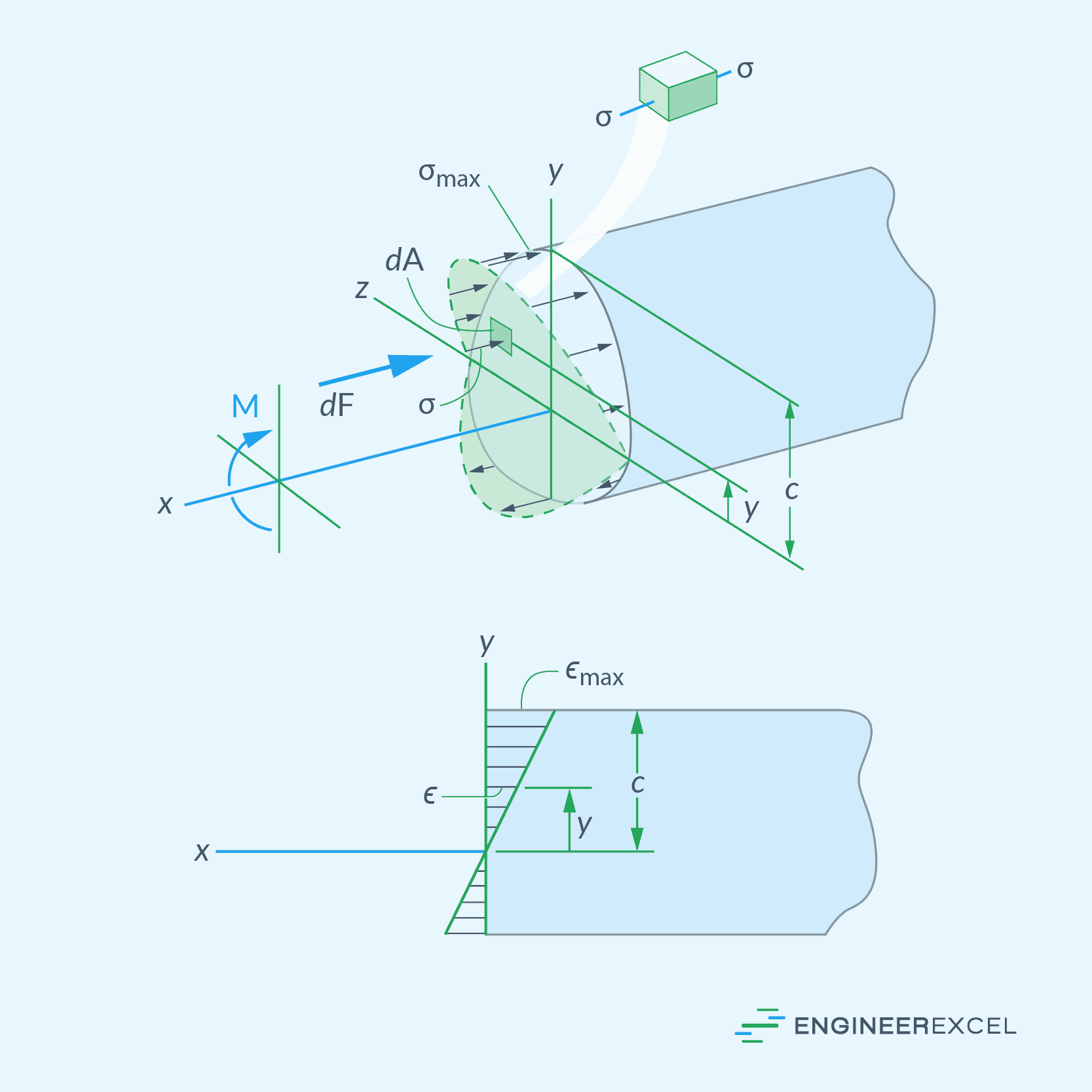
In the figure above, the upper section is experiencing compression, which means it has negative normal stress and strain. On the other hand, the lower section is under tension, which means it has positive normal stress and strain. However, it’s important to note that if the bending moment were to be reversed, the opposite would occur.
Determining the Neutral Axis Position
Determining the position of the neutral axis is important in calculating the distribution of stresses and strains in the material, which, in turn, helps engineers design structures that can safely withstand loads and maintain their structural integrity.
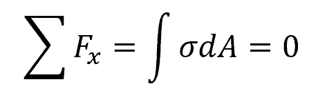
The position of the neutral axis depends on the cross-sectional geometry of the structure and the loading conditions. In general, we can locate this position by satisfying the condition that the resultant force produced by the stress distribution over the cross-sectional area equals zero, such that:
Where:
- Fx = internal normal forces due to the stress in the material [N]
- σ = normal stress in the material [Pa]
- A = cross-sectional area of the beam [m2]
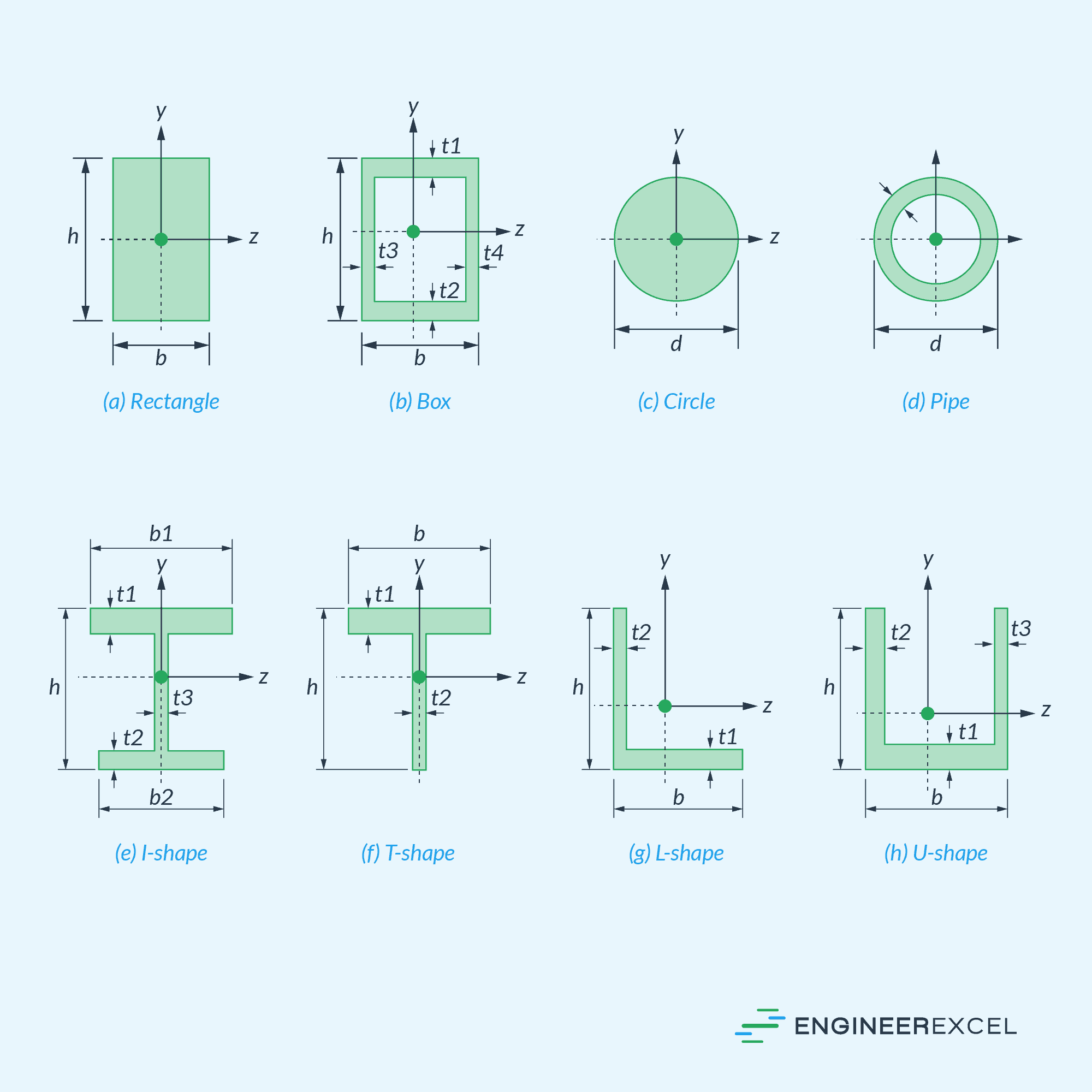
For a linearly elastic beam, this condition can be satisfied if the first moment of the cross-sectional area about the neutral axis is zero. In other words, the neutral axis passes through the centroid or the geometric center of the cross section, as shown in the diagram below.
However, it is important to note that the neutral axis and the centroidal axis may not always coincide. This is the case for beams undergoing nonlinear plastic deformation. As a beam is loaded beyond its elastic limit, the position of the neutral axis can shift either upward or downward in relation to the centroid, depending on the material’s ability to withstand additional tension or compression.
Orientation of the Neutral Axis
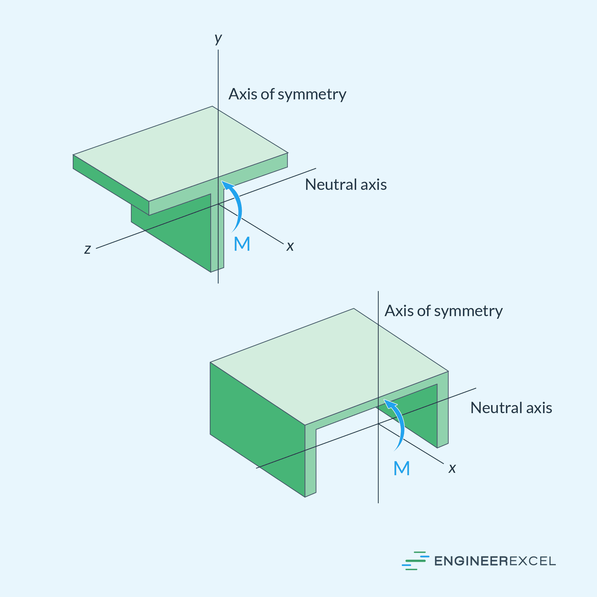
In the examples above, it was assumed that the resultant internal moment acts about one of the principal axes of the cross-section that is perpendicular to an axis of symmetry, as shown in the diagram below. In this case, the neutral axis will always be oriented along the said principal axis.
However, a member may sometimes be loaded such that the internal moment does not act about one of the principal axes of the cross section. This is called unsymmetric bending.
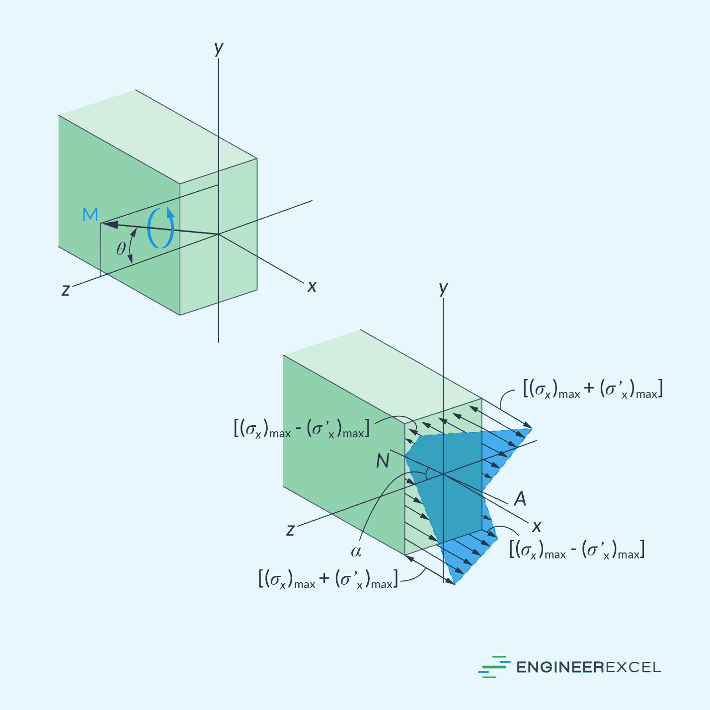
The diagram below shows an example of an unsymmetric bending where the internal moment makes an angle θ with the principal z axis.
In this case, the orientation of the neutral axis can be determined using the following formula:
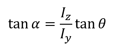
Where:
- α = angle of the neutral axis with respect to the principal z axis [rad]
- θ = angle of the internal moment with respect to the principal z axis [rad]
- Iz = principal moment of inertia about the z axis [m4]
- Iy = principal moment of inertia about the y axis [m4]