
Structural members with a curved profile, such as hooks, rings, or arches, are known as curved beams. Analyzing the bending stress in curved beams is different from analyzing straight members due to the inherent effect of curvature on stress distribution.
This article delves into the mechanics of bending stress in curved beams and the formula used to calculate normal stress in such members.
Understanding Bending Stress in Curved Beams
Curved beams are structural members that have a curved profile, often observed in structures like hooks, rings, or arches. Analyzing bending stress in curved beams differs significantly from analyzing straight members since their curvature inherently affects the stress distribution. While the flexure formula works well for straight members with a linear bending stress distribution, it becomes inaccurate when applied to curved beams.
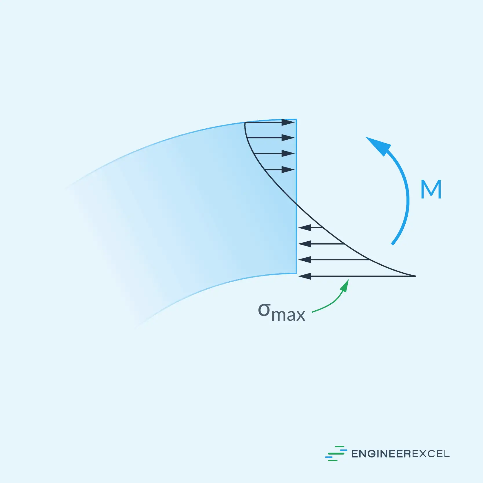
In curved beams, the neutral axis is not located at the centroid of the cross-section. This departure causes a hyperbolic stress distribution, shown in the diagram below, as opposed to the linear distribution found in straight beams.

Elevate Your Engineering With Excel
Advance in Excel with engineering-focused training that equips you with the skills to streamline projects and accelerate your career.
The curved-beam analysis is particularly crucial when analyzing members with pronounced curvature. A better understanding of the bending stress in curved beams allows engineers to design more reliable structures that can withstand the forces applied to them more effectively.
Two main assumptions are used to analyze the stress distribution in a curved beam. The first assumption is that the cross-section has an axis of symmetry in a plane along the length of the beam, and the second assumption is that plane cross sections remain planar after bending. The modulus of elasticity, which is a property of the material, is considered the same in tension and compression.
The bending stress distribution in curved beams is analyzed using the strength of materials approach. This approach assumes that plane sections rotate about the neutral axis and the only significant stress present is the hoop stress.
Bending Calculations for Curved Beams
Curved Beam Neutral Axis
The neutral axis of curved beams is important in understanding bending stress distribution. It is the plane along the length of the beam where stress is zero during bending.
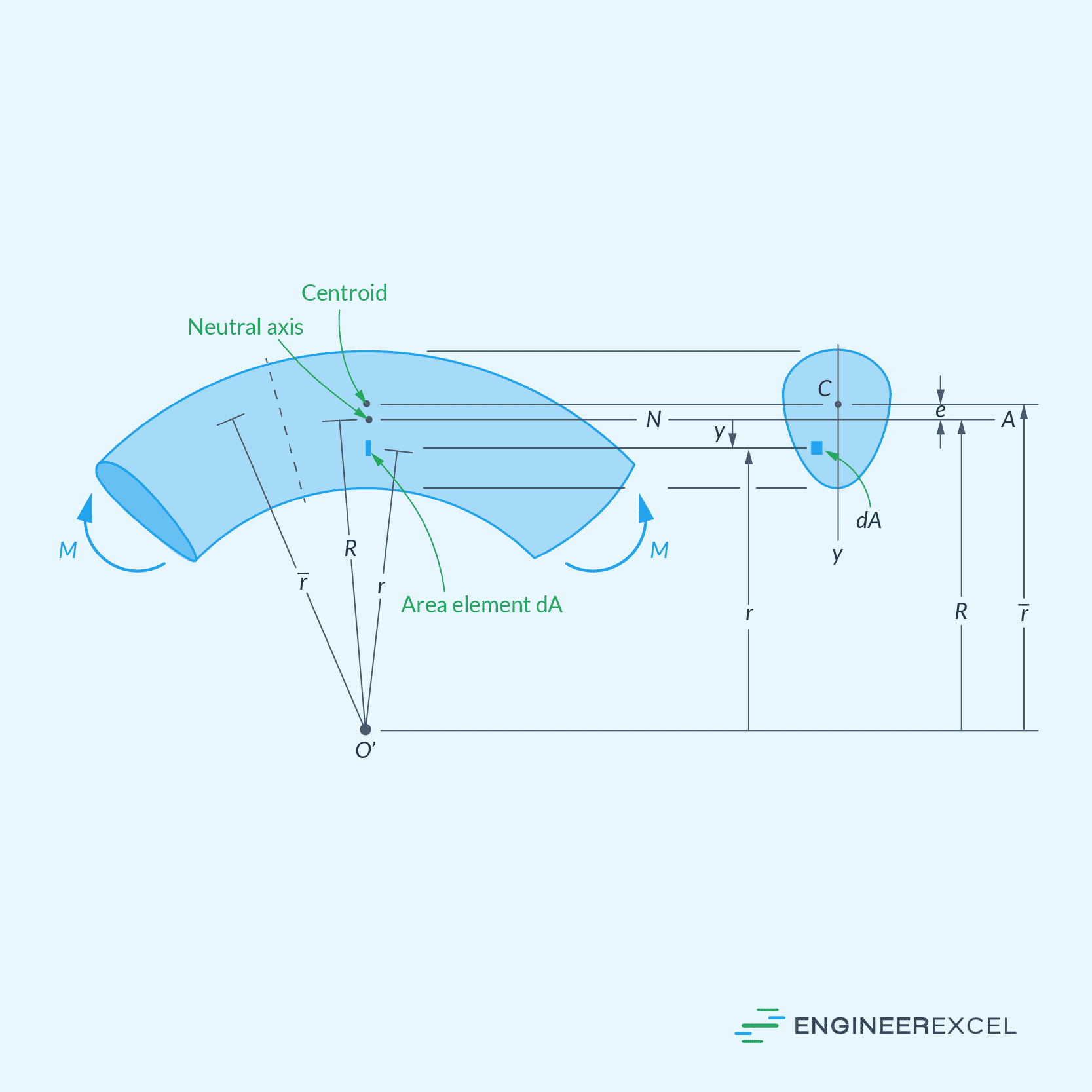
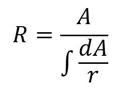
For a curved beam, the location of the neutral axis can be specified from the beam’s center of curvature by the following equation:
Where:
- R = distance of the neutral axis from the center of curvature [m]
- A = cross-sectional area of the beam [m2]
- r = arbitrary position of the area element dA, specified from the center of curvature [m]
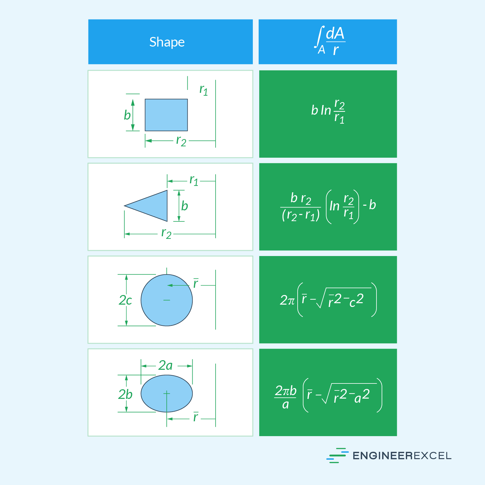
The integral in the denominator has been evaluated for various cross-sectional geometries. These are listed in the table below.
Curved Beam Formula for Normal Stress
Once the neutral axis is determined, the normal stress on the curved beam with respect to the distance measured from the center of curvature can be calculated using the following formula:
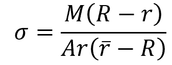
Where:
- σ = normal stress due to bending [Pa]
- M = internal moment about the neutral axis [N-m]
- r̄ = distance from the center of curvature to the centroid [m]
This is commonly referred to as the curved beam formula.
Similar to the flexure formula for straight beams, the curved beam formula can be used to determine the normal-stress distribution in a curved beam. This distribution is hyperbolic in nature, and is sometimes referred to as circumferential stress since it acts along the circumference of the beam, as shown in the diagram below.
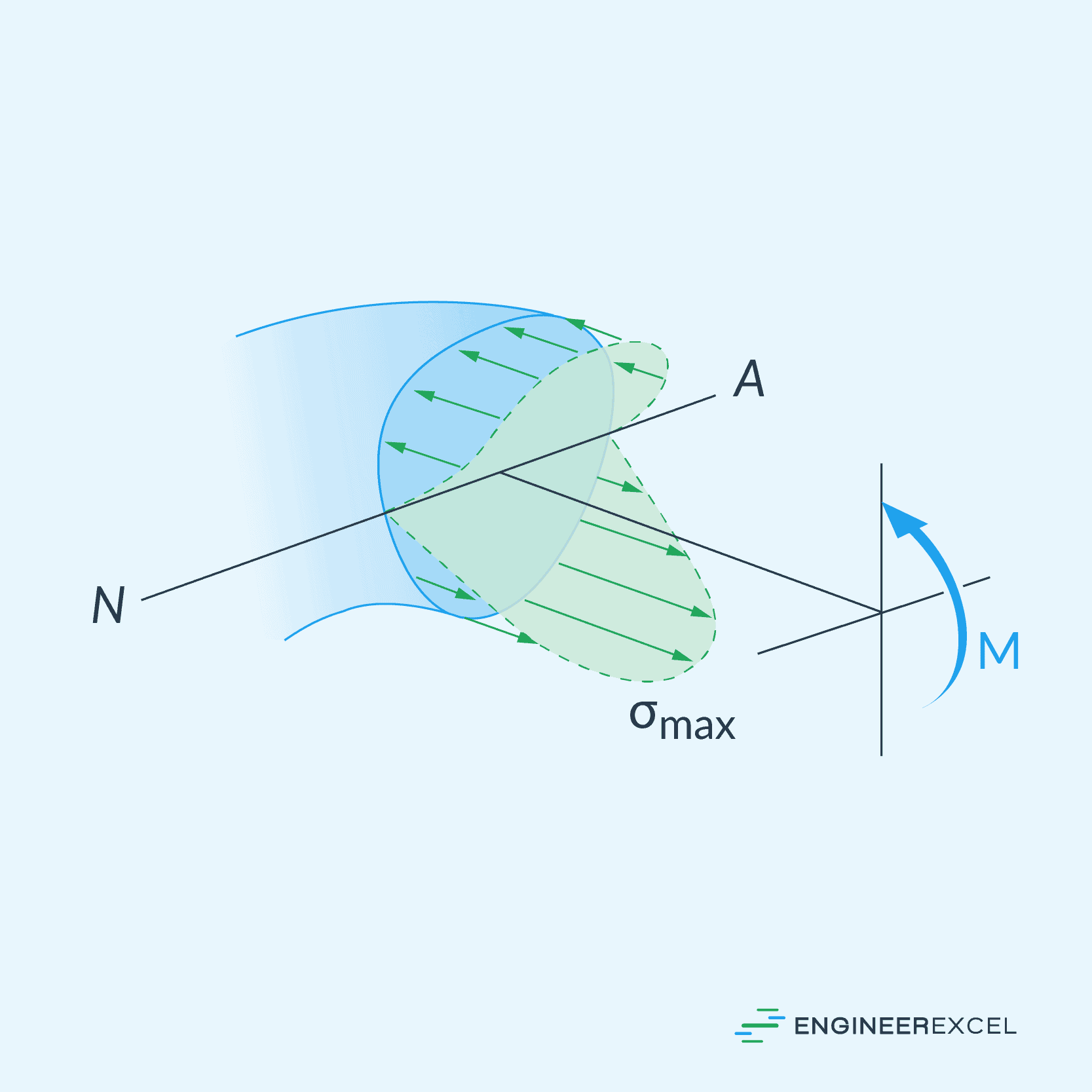
It is important to note that due to the curvature of the beam, a corresponding component of radial stress is created. For solid sections, these radial stresses are usually insignificant and can be ignored. However, in thin plate structures, the radial stress can be as large as the circumferential stress and must be considered in the design to ensure the member can withstand both stresses.
Applications and Limitations of the Curved Beam Formula
It is important to note that the curved beam analysis should only be used when the curvature of the member is pronounced enough to warrant it, such as in hooks or rings. That is, when the radius of curvature is less than five times the depth of the member. In these cases, the curved beam formula helps to determine the stress more accurately than the traditional flexure formula.
For less curved structures, the traditional straight beam analysis may be sufficient for obtaining accurate results. For example, for rectangular sections with a radius of curvature-to-depth ratio equal to 5, the maximum normal stress determined by the flexure formula will be around 7% less than its value as determined by the curved beam formula. The discrepancy diminishes further when the ratio exceeds 5.