
The area moment of inertia, also known as the second moment of area, is a geometric property that measures the stiffness of a two-dimensional shape or object. It describes the distribution of points within an area relative to an arbitrary axis, and is crucial for understanding how the area resists bending or deformation. In this article, we will explore the principles and methods involved in calculating the area moment of inertia.
Area Moment of Inertia Calculations
The area moment of inertia is a mathematical property that characterizes how an area is distributed around a chosen reference axis. It is a fundamental property that determines a cross-section’s ability to withstand bending, making it vital in the design and analysis of structures under bending or torsional loads.
The value of the moment of inertia depends on the specific reference axis selected. For example, the moment of inertia can differ when calculated about the x-axis versus the y-axis. In most practical cases, the centroidal axis is commonly chosen as the reference axis.
The notation for the area moment of inertia depends on the orientation of the axis relative to the plane of the area. When the axis lies within the same plane as the area, it is typically represented as I. However, when the axis is perpendicular to the plane, it is denoted as J.
It is important to note the area moment of inertia is different from the mass moment of inertia.

Elevate Your Engineering With Excel
Advance in Excel with engineering-focused training that equips you with the skills to streamline projects and accelerate your career.
Calculating Area Moment of Inertia by Integration
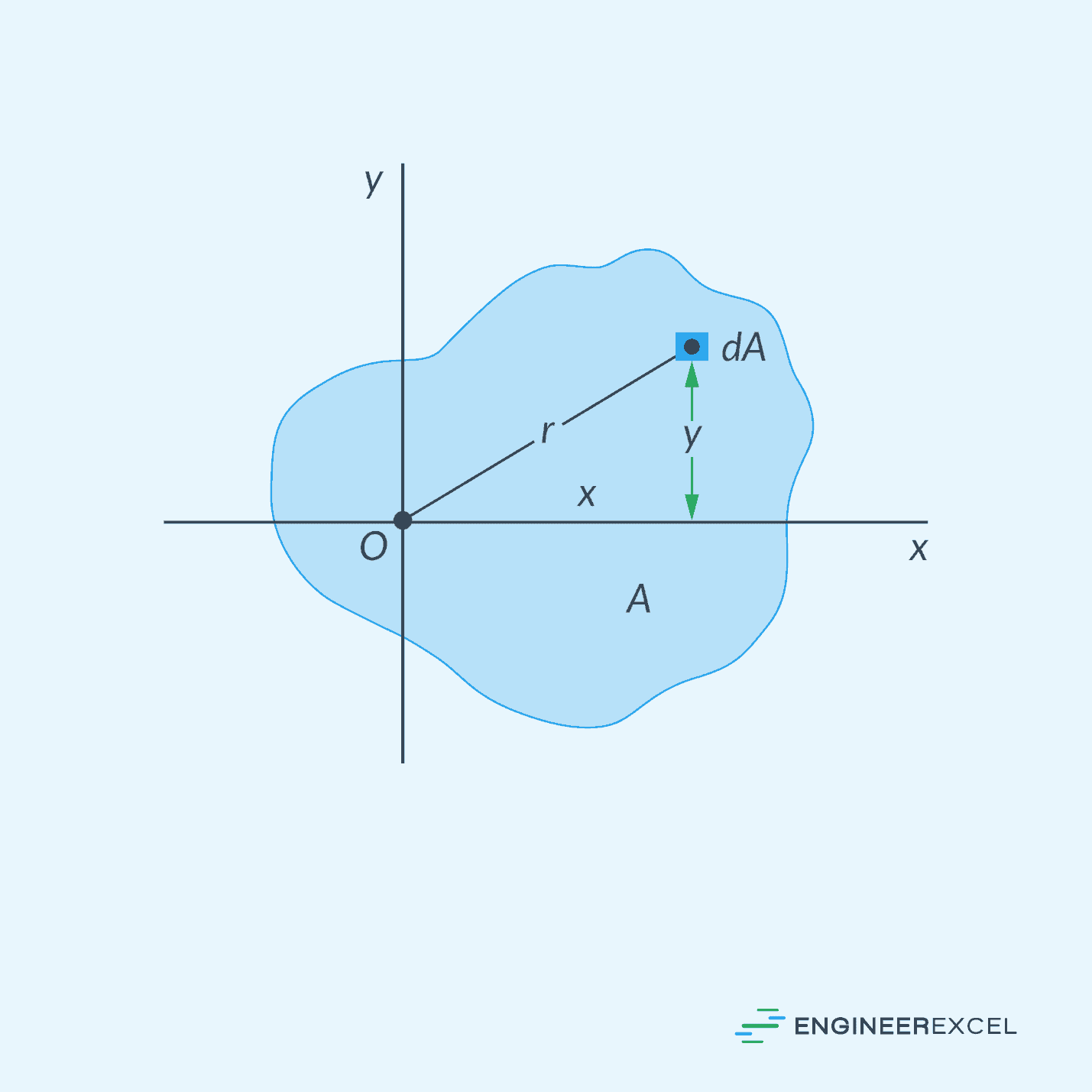
Mathematically, the area moment of inertia can be calculated by integrating the product of the square of the distance and the differential area element. This integration sums up the contribution of each infinitesimally small area element to the overall moment of inertia.
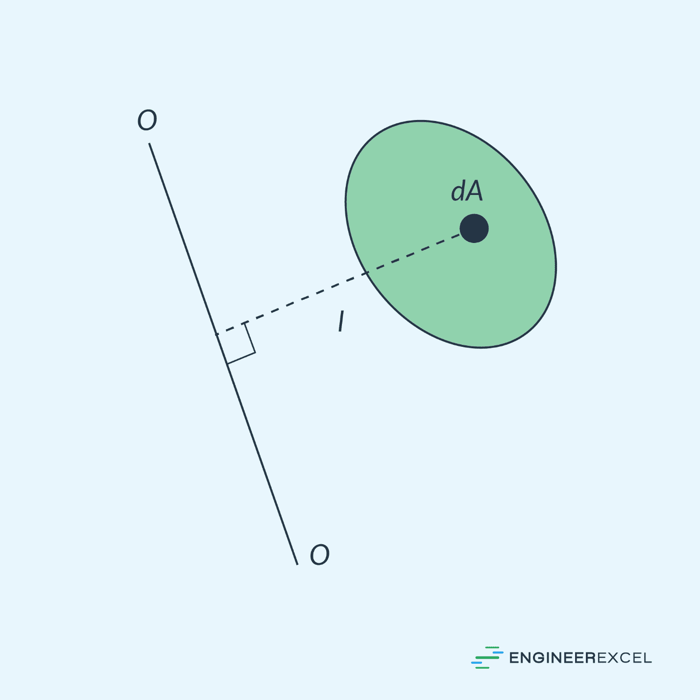
For example, for a circular plane, shown above, the area moment of inertia about the axis O-O can be calculated using the formula:
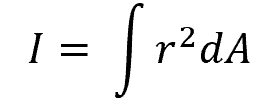
Where:
- I = area moment of inertia about an axis lying on the same plane [m4 or in4]
- r = distance of each area element from the reference axis [m or in]
- dA = infinitesimally small area element [m2 or in2]
Rectangular Moments of Inertia
In a rectangular coordinate system, obtaining the area moments of inertia around the x-axis and y-axis is often valuable. These moments are denoted as Ix and Iy, respectively, and are commonly referred to as the rectangular moments of inertia.
Instead of assuming a square-shaped differential area element, the rectangular moments of inertia can be more easily evaluated by assuming each area element to be a thin strip parallel to the reference coordinate axis, as shown in the figure below.
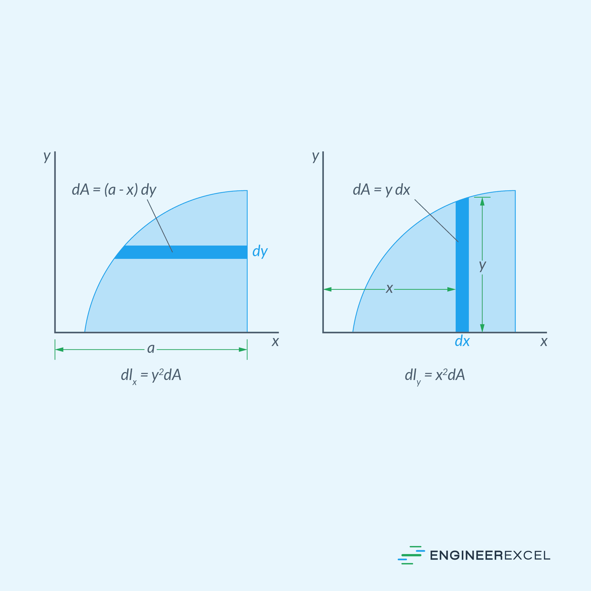
From the diagram above, the rectangular area moments of inertia can be calculated using the following formula:
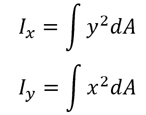
Where:
- Ix and Iy = area moment of inertia about the x- and y- axes, respectively [m4 or in4]
- x and y = distance of each strip area element from the y- and x- axes, respectively [m or in]
- dA = differential area of each strip element [m2 or in2]
Polar Moment of Inertia
Aside from the x- and y-axes, the area moment of inertia of a two-dimensional object can also be evaluated relative to its polar axis. The polar axis is the axis perpendicular to the plane that the object rotates around.
This polar moment of inertia holds significant importance in the analysis of torsional or rotational behavior of structural components like cylindrical shafts, beams, and gears. In addition, it determines the resistance to torsional deformation and helps engineers calculate the shear stresses and angular deflections caused by torsional loads.
Consider the area shown in the figure above. The polar moment of inertia can be calculated using the formula:
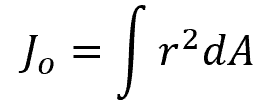
Where:
- Jo = polar moment of inertia [m4 or in4]
- r = distance of each differential area element from the polar axis O [m or in]
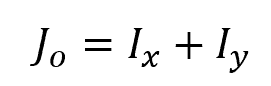
The polar moment of inertia can also be obtained by adding the rectangular area moments, as shown in the equation below:
Radius of Gyration
A very closely related concept to the area moment of inertia is the radius of gyration.
The radius of gyration, denoted by k, is an equivalent distance from the axis of rotation where the entire area can be concentrated to yield the same area moment of inertia. This is shown in the figure below.
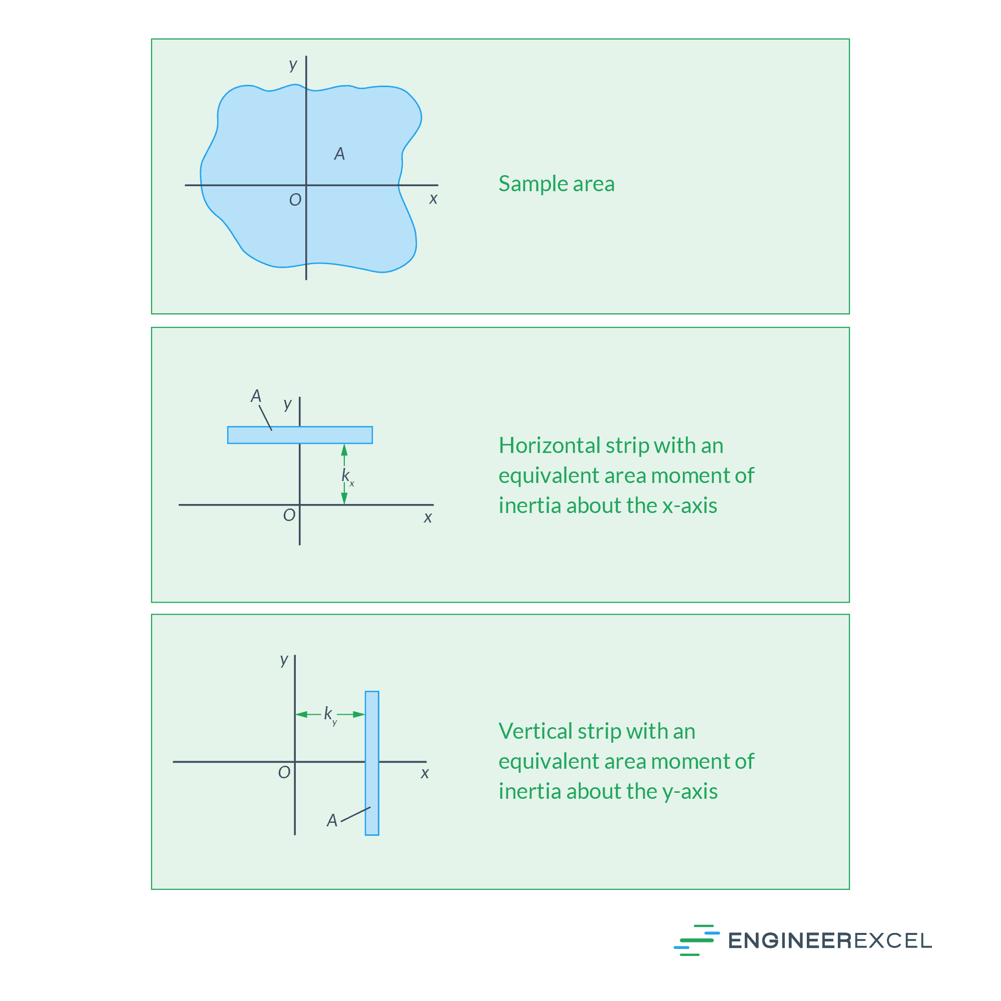
In simpler terms, it denotes the distance at which the shape needs to be concentrated to achieve identical rotational characteristics. Hence, it offers a convenient method to simplify calculations related to rotational or torsional problems.
The radii of gyration can be calculated using the following formulas:
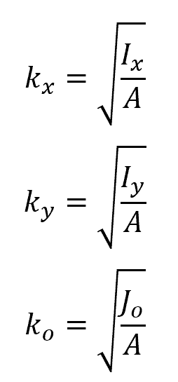
Where:
- kx, ky, and ko = radii of gyration with respect to x-, y-, and polar axes, respectively [m or in]
- A = total area of the shape [m2 or in2]
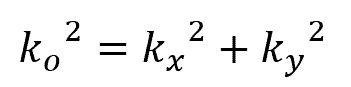
Just like the polar moment of inertia, the polar radius of gyration can also be derived from the rectangular radii of gyration using the formula:
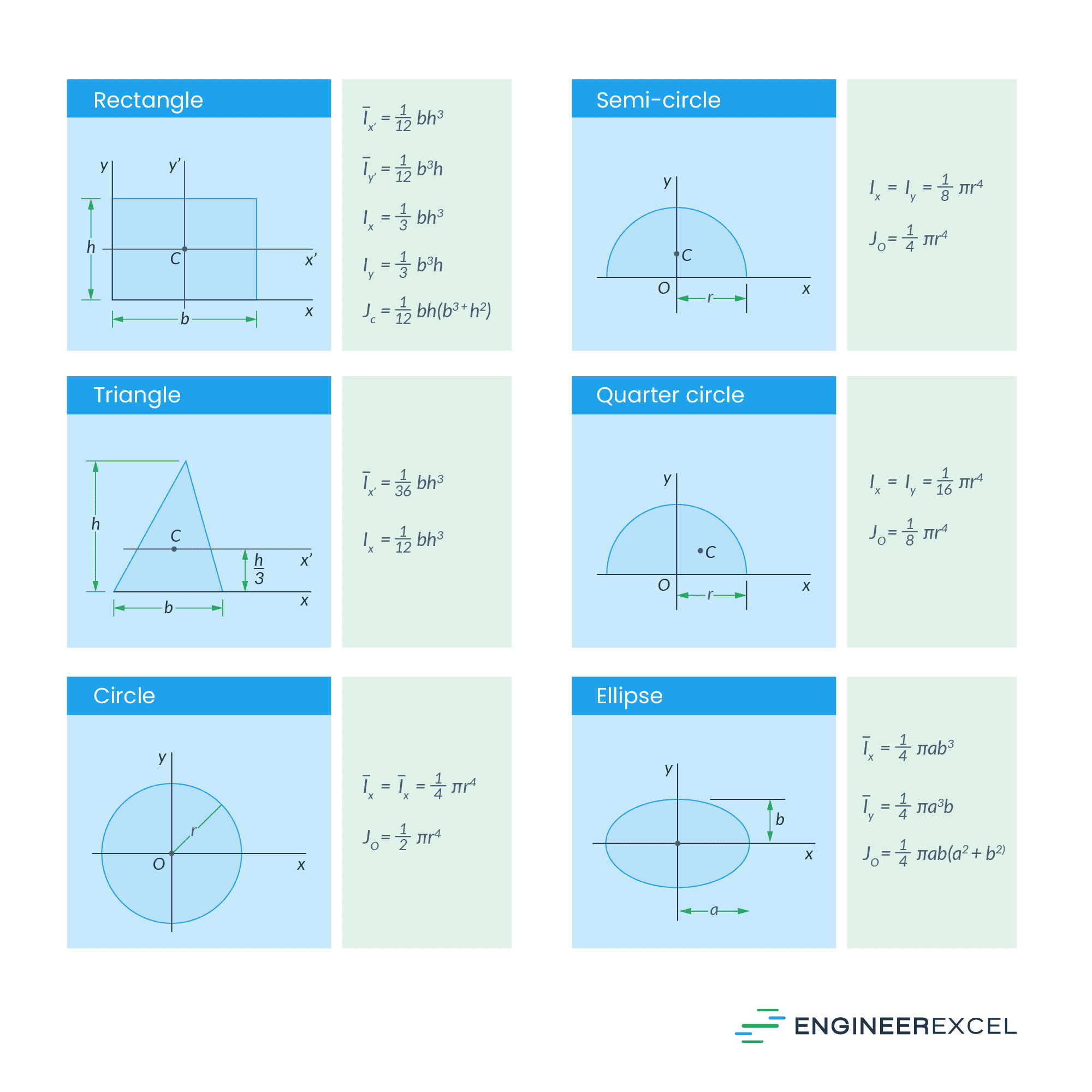
Area Moment of Inertia of Common Shapes
Engineers have established formulas to simplify the calculation of the area moment of inertia for common geometric shapes. These are summarized in the table below.
Parallel Axis Theorem
The parallel axis theorem, also known as Steiner’s theorem, is a principle that translate the area moment of inertia of an object about an axis passing through the centroid to a parallel axis located a certain distance away.
In essence, it states that the area moment of inertia of a shape about any axis can be obtained by adding its area moment of inertia about a parallel axis passing through the centroid to the product of its total area and the square of the distance between the two axes.
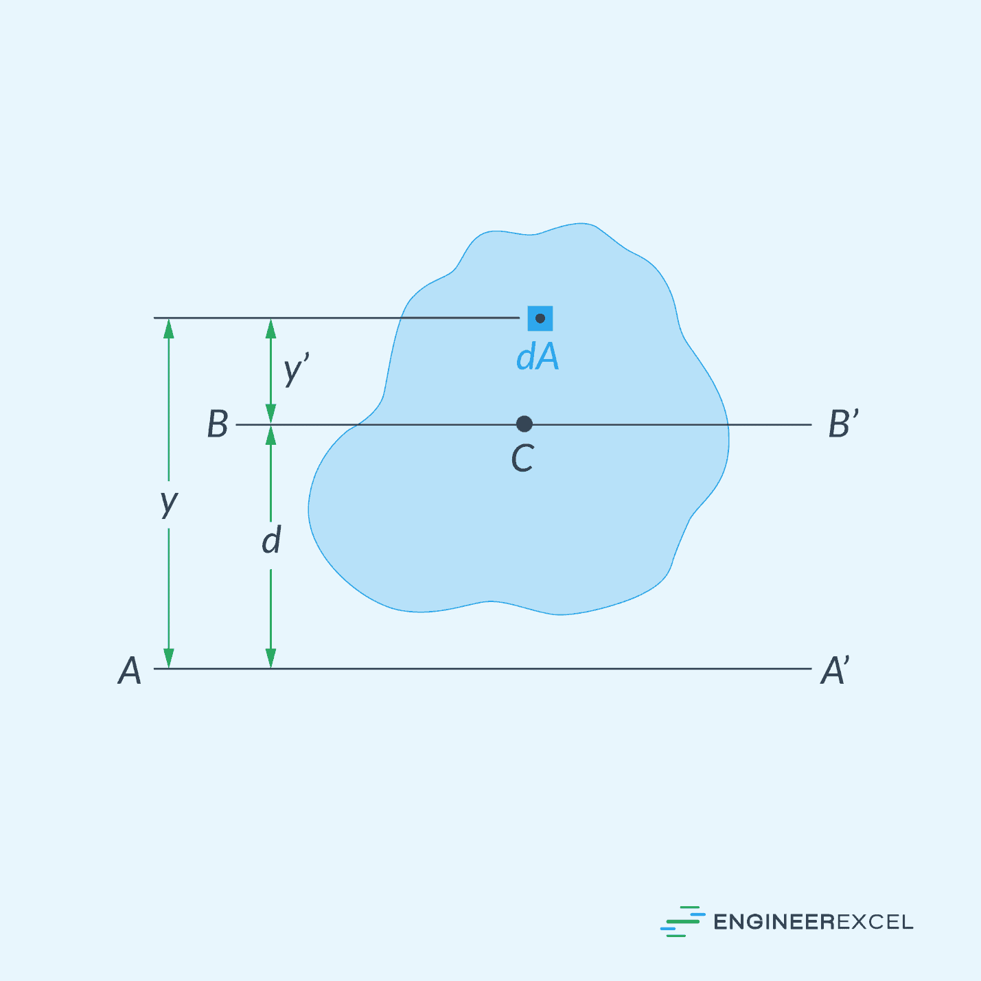
Consider the figure above. The area moment of inertia about the axis A-A’ can be derived from the area moment of inertia about its centroidal axis using the formula:
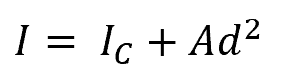
Where:
- I = area moment of inertia about axis A-A’ [m4 or in4]
- Ic = area moment of inertia about the centroidal axis [m4 or in4]
- d = distance between the centroidal axis and the A-A’ axis [m or in]
Note that this formula also applies to the polar moment of inertia. To get the polar moment of inertia about an arbitrary point O, use the equation:
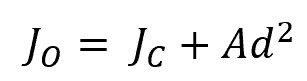
Where:
- JO = polar moment of inertia about an arbitrary point O [m4 or in4]
- Jc = polar moment of inertia about the centroid [m4 or in4]
Area Moment of Inertia of Composite Shapes
In line with the parallel axis theorem, it follows that the moment of inertia of a composite area about any axis is simply the sum of the moments of inertia of its individual component areas about the same axis.
Hence, when an area is added to an existing shape, its moment of inertia is added to the overall moment of inertia. Similarly, when an area is removed, such as creating a hole, its moment of inertia is subtracted from the moment of inertia of the larger shape.
This method is commonly employed in the analysis of structural elements that have cross-sectional areas that can be formed by combining familiar geometric shapes. Since established formulas already exist to determine the area moment of inertia for these common shapes, it is now easier to calculate the overall moment of inertia by simply summing the individual moments of inertia.
This method is one way to simplify the process of evaluating the moment of inertia for complex structures. For example, consider the figure below.
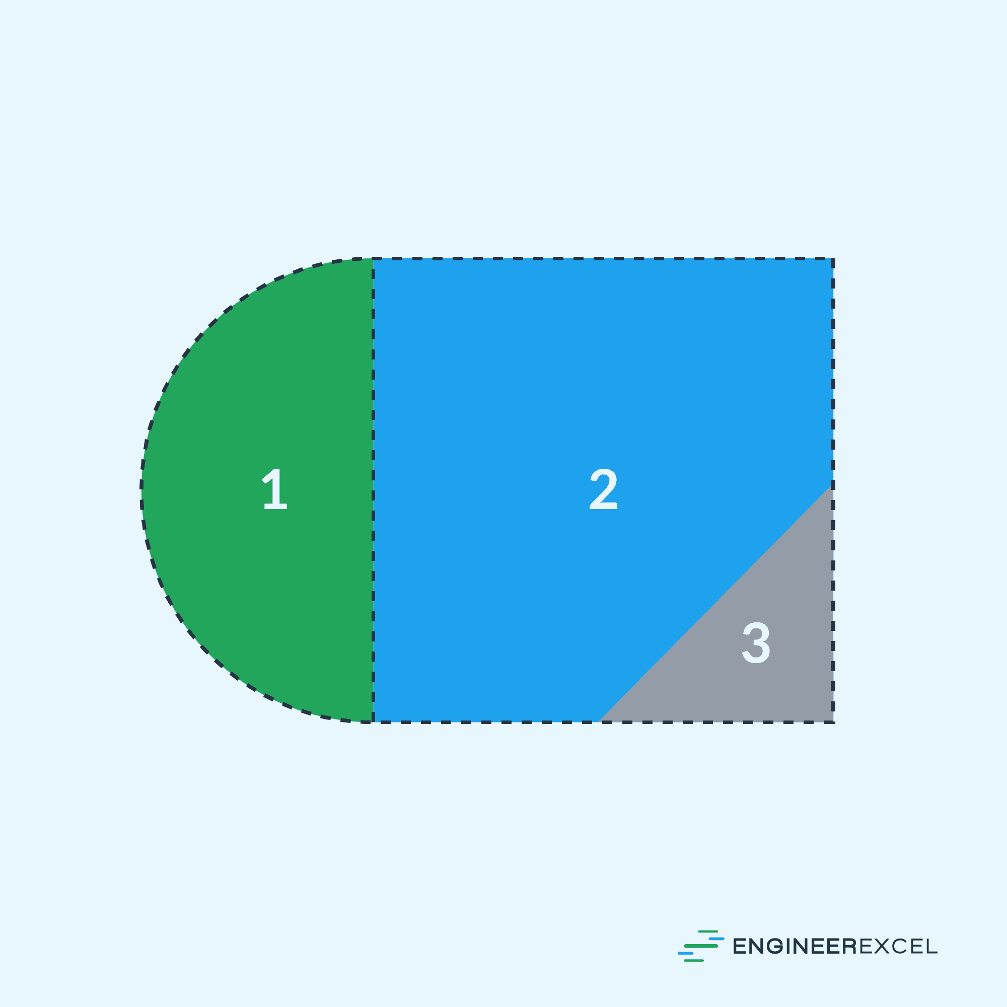
The overall moment of inertia of the composite area, shown above, can be obtained by summing the area moments of inertia of shapes 1 (semicircle) and 2 (square), and then subtracting the area moment of inertia of shape 3 (triangle).
This method is useful in practical applications, particularly because standard structural elements, like channels and I-beams, typically have cross-sectional areas that can be considered composite areas comprised of basic geometric shapes.