
The bending moment is the internal torque experienced by a beam when subjected to external loads. Understanding how this parameter varies along the axis of the beam is essential in designing safe structures. This article tackles the bending moment and how it affects the flexural stress in a beam.
Bending Moment Explained
The bending moment represents the internal torque experienced by a beam when subjected to external loads. To comprehend this phenomenon better, it is important to first understand the basics of beam structures and loading types.

A beam is generally used to support various structures, including the floor of a building, the deck of a bridge, or the wing of an aircraft. It is a horizontal structural element that primarily bears vertical loads. These loads result in internal forces and moments that cause the beam to deform.
There are two types of loading in beam structures: distributed loads and concentrated loads. Distributed loads are applied uniformly along the length of the beam, while concentrated loads are focused on specific points. The bending moment at any point along the length of the element is determined by the distribution and magnitude of the applied loads, as well as the geometry and material properties of the element.

Elevate Your Engineering With Excel
Advance in Excel with engineering-focused training that equips you with the skills to streamline projects and accelerate your career.
Mathematically, bending moment is the algebraic sum of the moments applied to the beam at any point along its length. It is calculated by multiplying the force acting on the beam by the distance from the beam’s end to the point at which the bending moment is required.
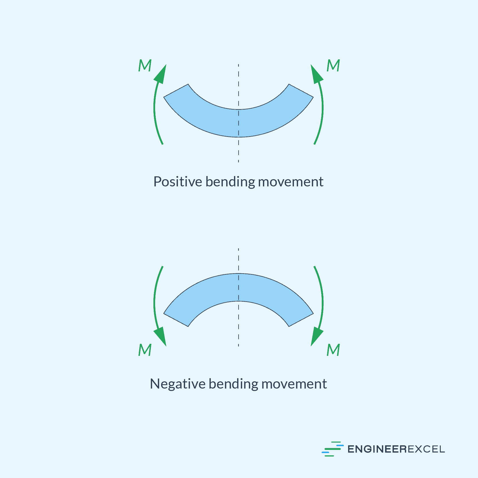
Bending moments can be positive or negative depending on the specific conditions and forces acting on the structural element. By convention, a positive bending moment occurs when the applied forces and moments cause the structural element to bend or flex in a way that the top of the element is in compression and the bottom is in tension. In a simply supported beam, a positive bending moment usually occurs when a load or force is applied above the beam, creating a sagging or concave shape.
On the other hand, a negative bending moment occurs when the applied forces and moments cause the top of the structural element to be in tension and the bottom to be in compression. In a simply supported beam, a negative bending moment typically occurs when a load or force is applied below the beam, creating a humped or convex shape.
These are illustrated in the diagram below:
Bending Moment Diagram
In general, the bending moment varies from point to point along the axis of the beam. In order to design a structurally safe beam, it is important to determine the maximum bending moment that is experienced by the beam and where it occurs. One way to do this is by creating a bending moment diagram.
A bending moment diagram is a graphical representation of the variation in bending moment along the length of the beam. It is typically plotted along the horizontal axis, which represents the length of the structural element, while the vertical axis represents the magnitude of the bending moment.
One method commonly used to draw bending moment diagrams is the superposition method. This involves breaking down the complex load system on the beam into simpler components and subsequently combining their effects. Shear and moment diagrams for each single load can be drawn separately, and then summed to obtain the overall diagrams.
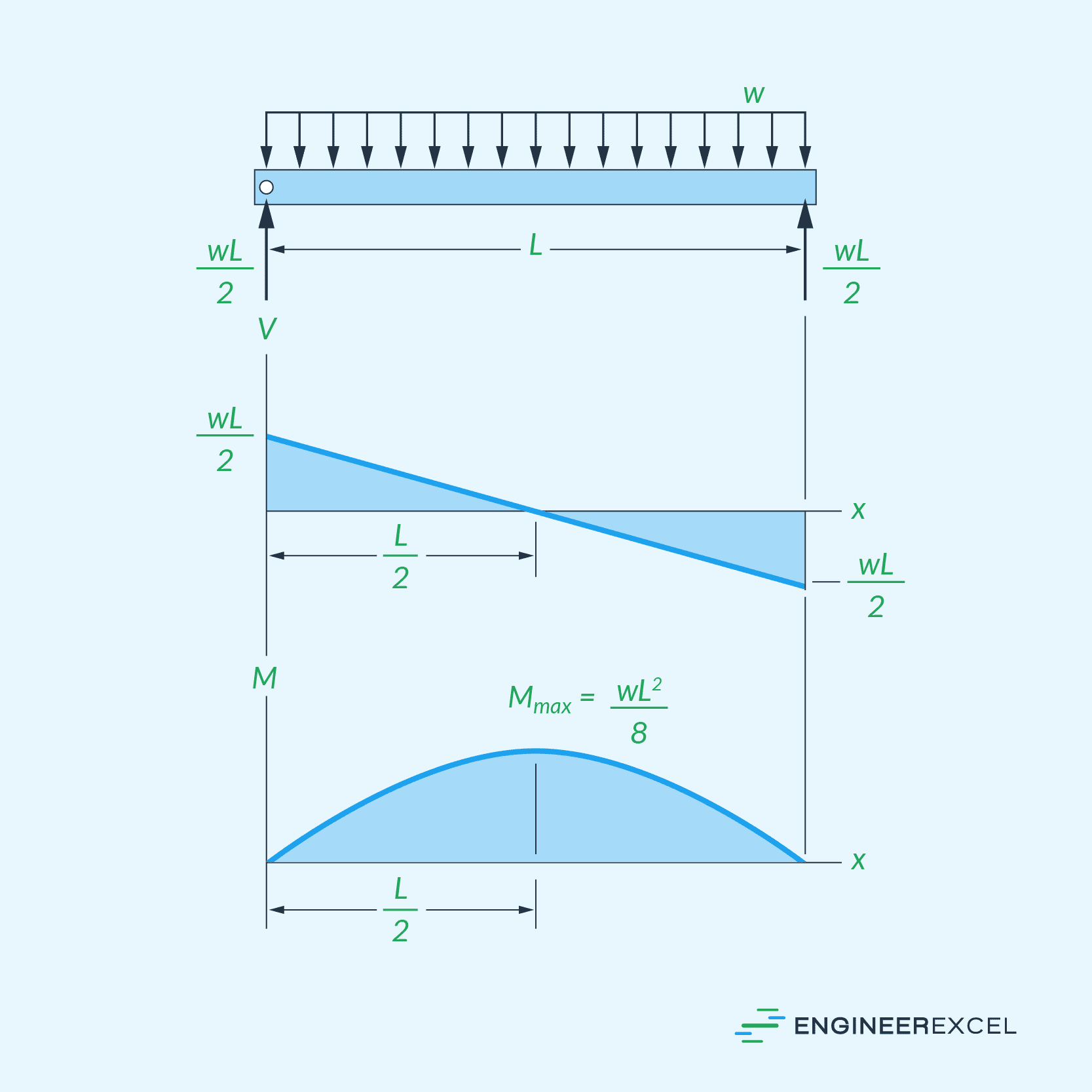
As an example, the diagram below shows the shear and bending moment diagrams of a beam with a uniformly distributed loading.
In addition to superposition, the area method is another technique for constructing bending moment diagrams. This method is based on the concept that the area under the shear force diagram between two points on a beam equals the change in bending moment between those two points.
When analyzing bending moment diagrams, it is crucial to consider the sign conventions. Generally, clockwise moments are considered negative, and counterclockwise moments are considered positive. Shear forces that generate clockwise moments are designated as negative, while those causing counterclockwise moments are assigned positive values.
Bending moment diagrams are typically used to identify areas of the structure that experience the most significant forces. This helps in distributing loads and designing reinforcement at critical points to prevent structural failure.
Effect of Bending Moment on Flexural Stress
Flexural stress is a type of mechanical stress that occurs when a beam is subjected to a bending moment, which causes the object to deform and bend. Bending stress can be tensile or compressive, depending on whether the material on one side of the beam is stretched or compressed relative to the other side.
In beams subjected to just bending, a linear relationship between bending moment and the flexural stress is observed, as expressed in the following equation:
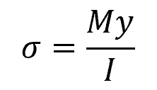
Where:
- σ = bending stress [Pa]
- M = bending moment [N-m]
- y = distance from the neutral axis to the point at which the stress is being calculated [m]
- I = moment of inertia [m4]
Bending stress is a critical factor in the design and analysis of structures and beams, as it helps determine whether a given structure or component can safely support the loads and moments to which it will be subjected.