Bending stress is a type of stress that occurs when a structure is subjected to a bending moment and deforms. If the applied moment causes the material to deform beyond its elastic limit, the linear-elastic equations become inapplicable, and plastic analysis is necessary to determine the stress distribution. In this article, we will discuss how the stress distribution behaves in plastic bending and how to calculate bending stress for plastic deformation.
Understanding Plastic Bending Stress
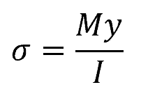
Bending stress is the normal stress experienced by a structure undergoing deformation due to a bending moment. Within the linear-elastic region of the material, stress is directly proportional to strain, and the normal stress due to bending can be described by the following equation:
Where:
- σ = normal stress due to bending [Pa]
- M = applied bending moment [N-m]
- y = distance from the neutral axis to the point at which the stress is being calculated [m]
- I = moment of inertia [m4]

Elevate Your Engineering With Excel
Advance in Excel with engineering-focused training that equips you with the skills to streamline projects and accelerate your career.
However, when the applied moment causes the material to yield and deform past the elastic limit, the linear-elastic equations become inapplicable, and plastic analysis is required to determine the stress distribution. This phenomenon is known as plastic or inelastic bending.
In general, analyzing the bending stress distribution of materials undergoing plastic deformation revolve around three key conditions. First is that normal strains vary linearly from zero at the neutral axis of the cross-section to a maximum at the farthest point from the neutral axis. This linear variation is the basis for establishing stress distribution across the beam’s cross-sectional area.
The second condition is, if only a resultant internal moment acts on the cross-section, the resultant force caused by stress distribution must be equal to zero. This condition is utilized to obtain the location of the neutral axis.
Lastly, the moment at the section must be equivalent to the moment caused by the stress distribution about the neutral axis. This condition ensures that the beam’s internal response is adequate to resist the externally applied moment.
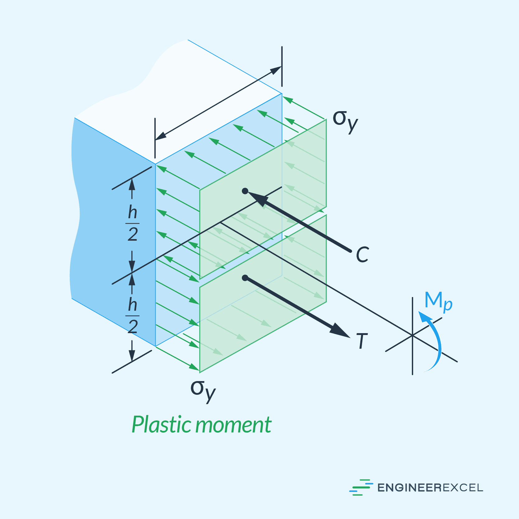
To illustrate how the stress distribution behaves in plastic bending, consider a beam with a rectangular cross-section of height h and width b, as shown in the diagram below. The moment, MY, is the minimum moment that must be surpassed to cause plastic yielding.
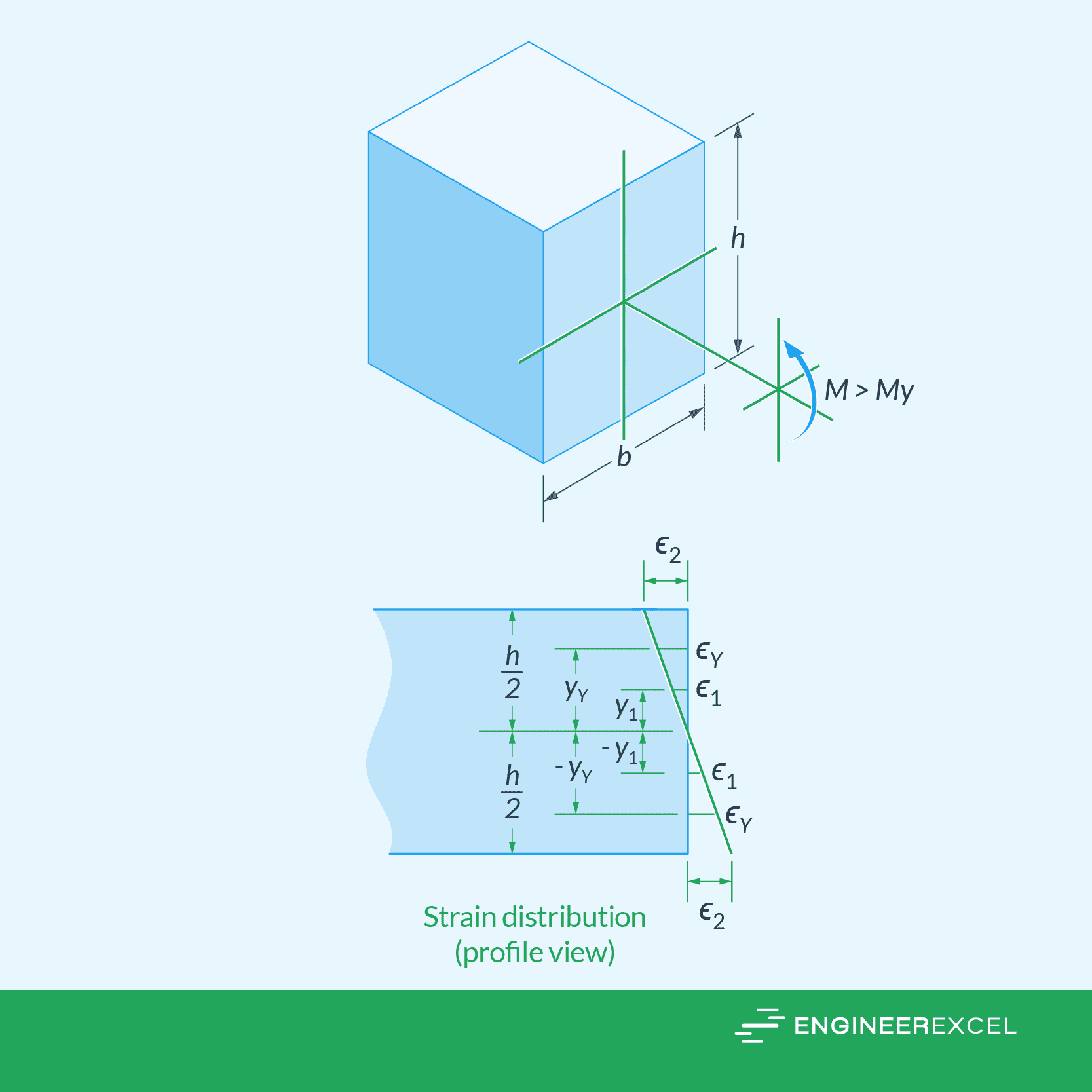
There are two possible scenarios that could happen depending on the magnitude of the moment applied. First is, if the applied moment is larger than MY but is not sufficient to plastically deform the whole cross-section, it would produce two zones of plastic yielding at the top and bottom sections, and an elastic section at the center. This is shown in the diagram below.
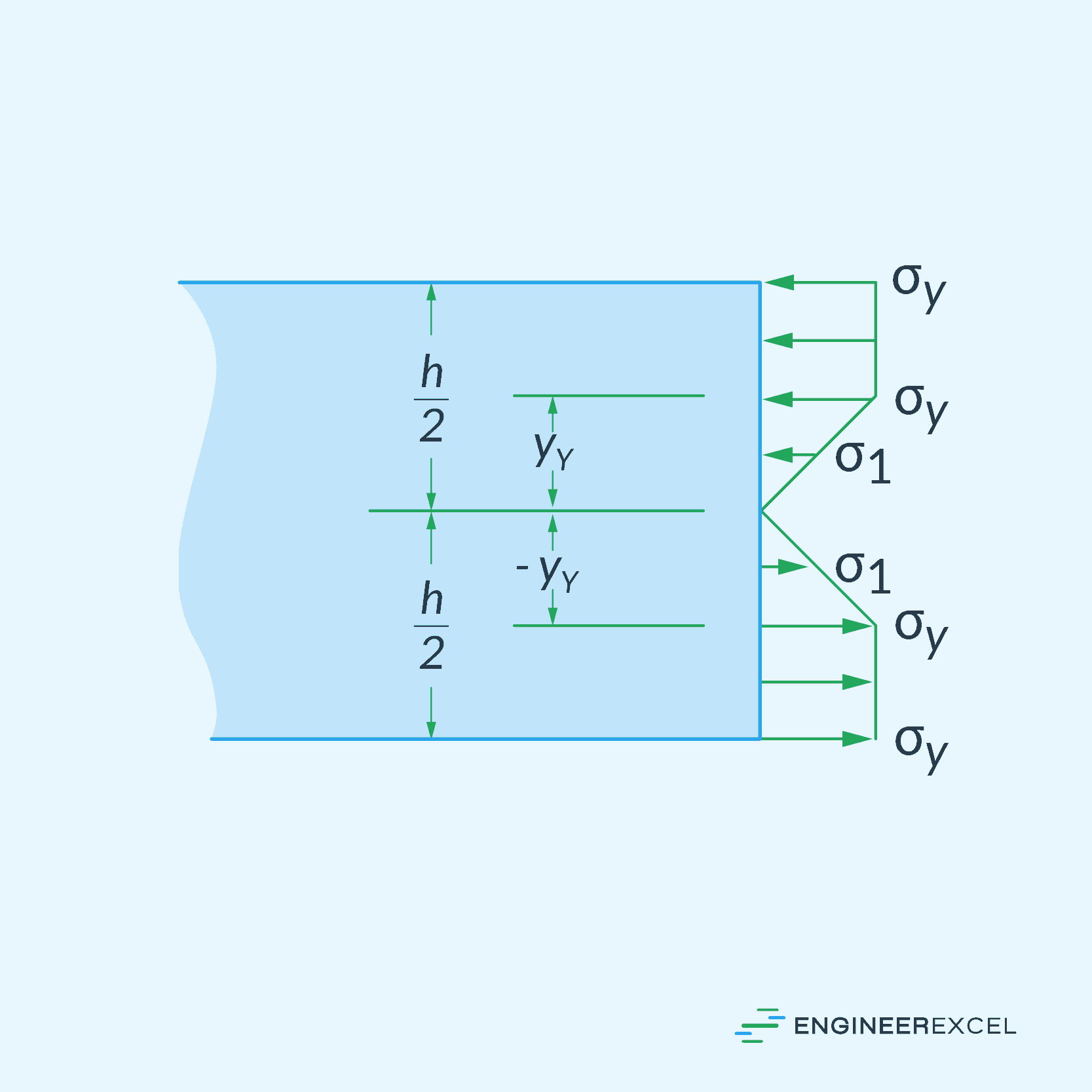
In a perfectly plastic behavior, it is assumed that the normal stress distribution is constant over the cross section, and the beam will continue to bend, with no increase in moment. This is the reason why the top and bottom plastic sections in the diagram above have a constant normal stress equal to σY.
As the applied moment increases in magnitude, the size of the elastic section decreases. The magnitude of the moment at which this elastic section completely vanishes and the whole cross-section starts to deform plastically is called the plastic moment. At this point, the stress distribution becomes fully uniform, as shown in the diagram below.
Bending Stress Calculations for Plastic Deformation
Minimum Moment for Plastic Deformation
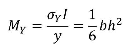
The minimum moment that must be surpassed to produce plastic yielding can be determined using the flexure formula. For a rectangular beam, it can be calculated using the following equation:
Where:
- MY = minimum moment for plastic deformation [N-m]
- σY = maximum normal stress due to inelastic bending [Pa]
- b = width of the beam [m]
- h = height of the beam [m]
Plastic Moment
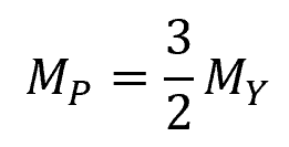
The plastic moment, or the magnitude of the moment at which the whole cross-section starts to deform plastically, can be calculated by finding the moments of the stress blocks around the neutral axis. For rectangular beams, it can be calculated using the following formula:
Where:
- MP = plastic moment [N-m]
Shape Factor
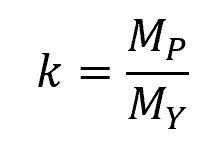
Beams are sometimes constructed to withstand a plastic moment. In such cases, codes specify a design property for the beam known as the shape factor. The shape factor is defined as:
Where:
- k = shape factor [unitless]
The shape factor indicates the extra moment capacity that the beam can handle beyond its maximum elastic moment.
Residual Stress in Plastic Deformation
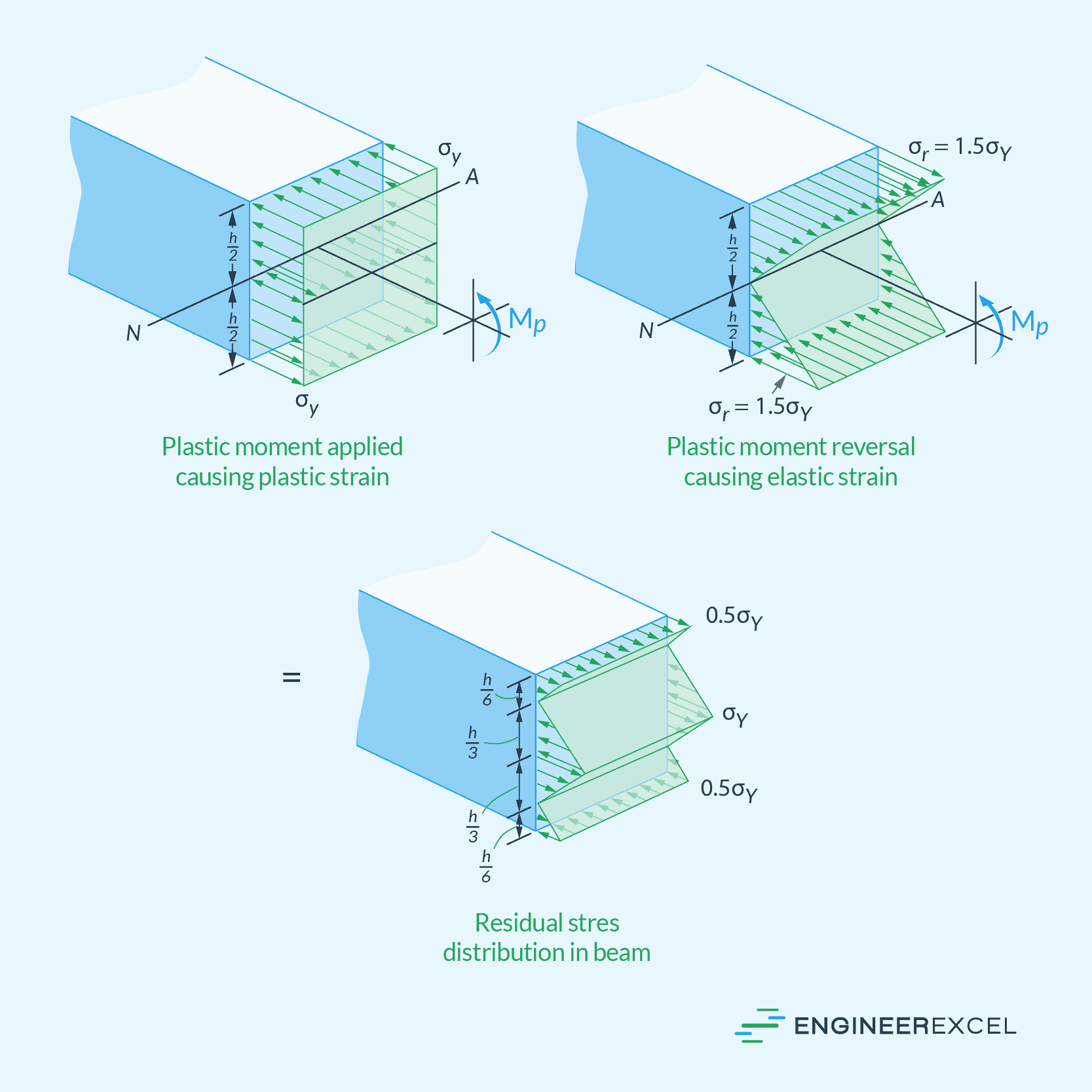
Residual stress can develop in a beam when a plastic moment is removed. This is significant when examining fatigue.
If the material at the top and bottom of a beam is plastically strained due to an applied moment, releasing that moment will cause the material to recover some of that strain elastically. The superposition of the plastic moment and its removal gives the residual-stress distribution, shown in the diagram below.