
Featured Fluid Dynamics Resources
[no_toc]
Mass Flow Rate: Calculation and Measurement
What is Head Pressure: Understanding Fluid Pressure in Engineering Systems

Hydraulic Gradient Line: Illustrating Hydraulic Energy in Fluid Systems
Flow Measurement: An Overview of Methods and Applications

Total Pressure in Fluid Dynamics Explained
Volume Flow Rate: Understanding and Calculation in Fluid Systems
Static Pressure Equation: Understanding Forces in Fluids at Rest
Dynamic Pressure: Understanding Forces in Moving Fluids
Free Jet Analysis: Understanding Its Fluid Dynamics

Stagnation Pressure: Understanding Pressure at Stagnation Point
Energy Gradient Line: Visualizing Total Energy in Fluid Flow
Fluid dynamics is the study and analysis of how fluids, including liquids and gases, behave and interact under various forces and in different conditions. It is a sub-discipline of fluid mechanics, which encompasses both fluid statics (the study of fluids at rest) and fluid dynamics.
In this article, we will explore fundamental concepts and equations in fluid dynamics, including Continuity and Bernoulli equations, static, dynamic, and stagnation pressures, hydraulic and energy grade lines, flow measurement, water hammer, and free jets.
Fundamental Equations in Fluid Dynamics

Elevate Your Engineering With Excel
Advance in Excel with engineering-focused training that equips you with the skills to streamline projects and accelerate your career.
The behavior of fluid particles under various physical conditions is described by several key equations that govern fluid flow. These equations include the Continuity Equation and the Bernoulli Equation.
Continuity Equation
The Continuity Equation reflects the principle of conservation of mass in fluid dynamics. For a fluid in motion, this equation asserts that the mass flow rate must remain constant from one cross-section of a conduit to another. Mathematically, it can be expressed as:
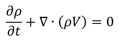
Where:
- ρ = fluid density [kg/m3]
- t = time [s]
- V = fluid velocity vector [m/s]
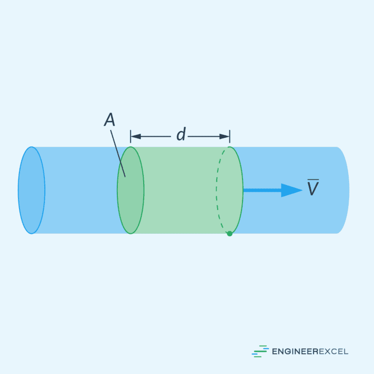
In one-dimensional incompressible flow, where density is constant, the equation simplifies to the invariance of the product of the cross-sectional area and fluid velocity, summarized as:
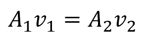
Where:
- A1, A2 = cross-sectional area of the flow at two different points [m2]
- v1, v2 = fluid velocity at two different points [m/s]
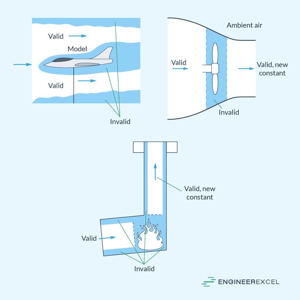
Bernoulli Equation
The Bernoulli Equation is a statement of the conservation of energy for flowing fluids. It relates the pressure, velocity, and elevation of a fluid particle to be constant along a streamline under conditions where viscous effects are negligible. The form suitable for many applications is:
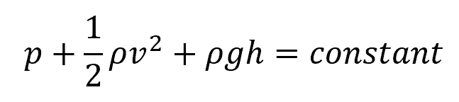
Where:
- p = static pressure [Pa]
- v = fluid velocity [m/s]
- g = gravitational acceleration [9.81 m/s2]
- h = elevation head [m]
This equation can be derived from the Navier-Stokes equations for the special case of steady, incompressible flow with no frictional losses, and is immensely useful for deriving the behavior of fluids in various contexts, such as in piping systems and airfoils.
Pressure Components in Moving Fluids
In many incompressible flows, elevation changes are negligible. Thus, the Bernoulli equation can be reduced to a balance between pressure and kinetic energy. In this case, the energy of a moving fluid can be divided into two components: static pressure and dynamic pressure.
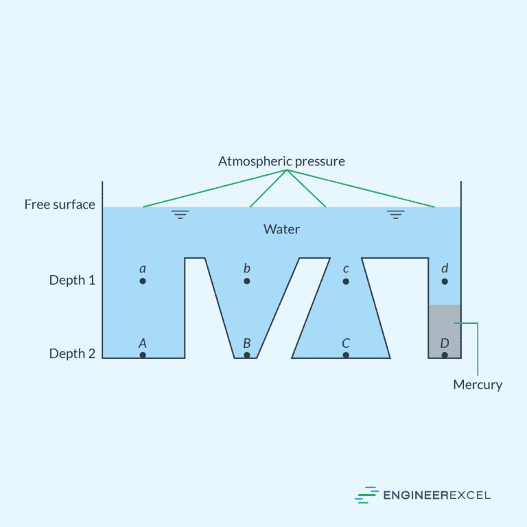
Static Pressure
Static pressure in moving fluids refers to the pressure exerted by the fluid particles when they come to rest in a streamline. It is the pressure that a fluid exerts perpendicular to the direction of flow and is not associated with the fluid’s motion. In closed systems, static pressure reflects the fluid’s exertion on container walls; for instance, in hydraulic systems.
Dynamic Pressure
On the other hand, dynamic pressure quantifies the fluid’s kinetic energy per unit volume. It is the pressure exerted in the direction of flow due to the fluid’s velocity. Dynamic pressure can be expressed by the formula:
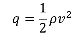
Where:
- q = dynamic pressure [Pa]
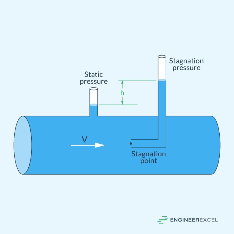
Stagnation or Total Pressure
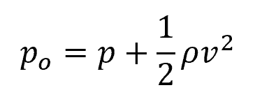
Stagnation pressure, also known as total pressure (po), combines the static and dynamic components and represents the pressure a fluid would exert when brought to a stop from its velocity. It is given as:
Knowing the stagnation pressure is important in analyzing fluid flow, particularly in scenarios involving compressible fluids or high-speed flows. In aerodynamics, stagnation pressure is used to assess the total pressure at a stagnation point, providing critical insights into the behavior of airflow around objects such as aircraft wings and bodies. Additionally, in the design and operation of propulsion systems, stagnation pressure is a key parameter for optimizing engine performance and efficiency.
Grade Lines
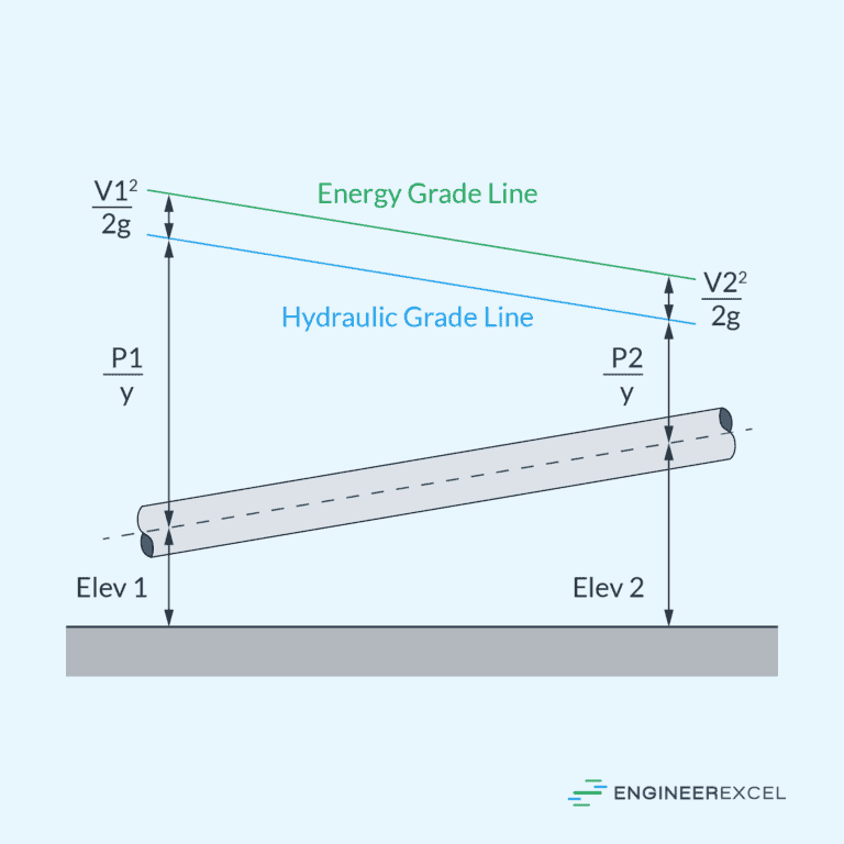
In the study of fluid dynamics, the Energy Gradient Line (EGL) and the Hydraulic Gradient Line (HGL) are two essential tools used to understand the behavior of water flowing through pipes and open channels.
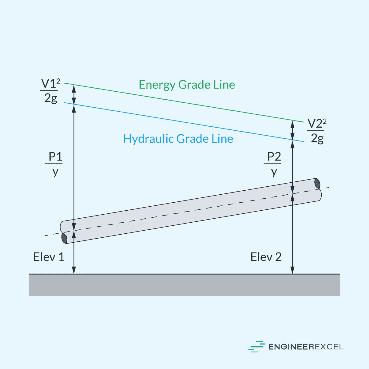
Energy Gradient Line
The Energy Gradient Line represents the total energy within a fluid system per unit weight of the fluid above any datum level. Technically, it is composed of the potential, kinetic, and pressure energies. Mathematically, the EGL is depicted by the famous Bernoulli’s equation, and it can be expressed as:
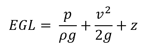
The first term (p/ρg) denotes pressure head, the second term (v2/2g) indicates velocity head, and the last term (z) is the elevation head. The EGL helps to determine the energy available to the fluid at different sections along the system and is essential when analyzing head losses due to friction or other factors in pipe flows.
Hydraulic Gradient Line
The Hydraulic Gradient Line, on the other hand, represents the available pressure head of the fluid flow in the pipe system. It can be defined as the sum of the pressure head and the elevation head:
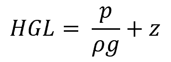
The HGL is always located below the EGL because it does not include the velocity head component. This line is essential for determining the piezometric height of the water at various points and is critical when designing systems to avoid issues such as pipe bursting or backflow.
Flow Measurement
Flow measurement is the quantification of the movement of a fluid, such as liquid or gas, through a conduit or system. It is important in various industries to monitor and control the flow of substances for processes like manufacturing, water distribution, and energy production. Two principal metrics are employed to characterize fluid flow: volume flow rate and mass flow rate.
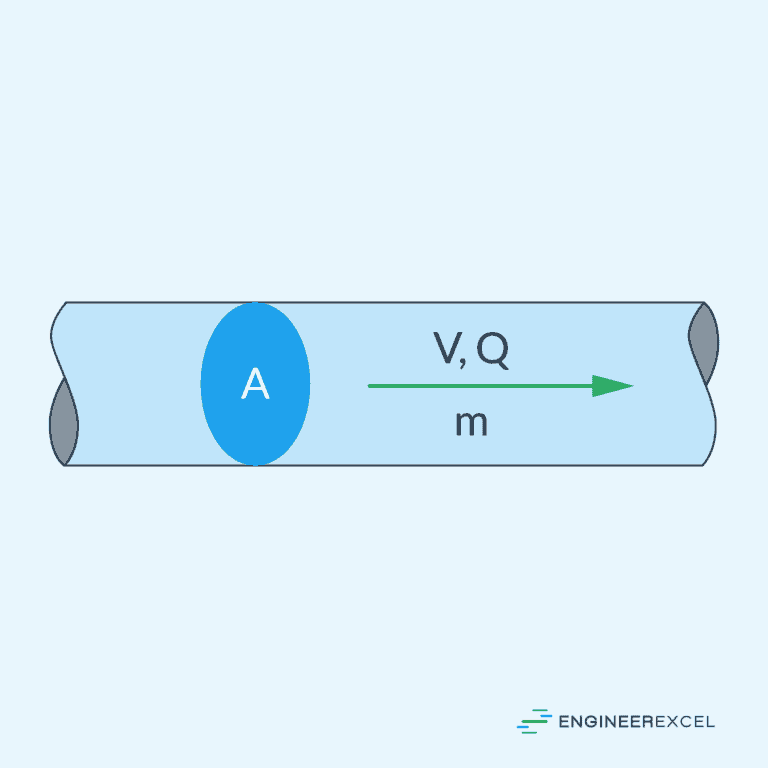
Volume Flow Rate
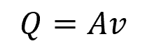
Volume flow rate measures the volume of fluid passing through a section per unit time. It can be calculated using the formula:
Where:
- Q = volume flow rate [m3/s]
- = cross-sectional area of the flow [m2]
Mass Flow Rate
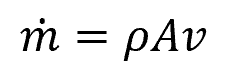
In contrast, mass flow rate refers to the amount of mass passing through a given cross-sectional area per unit time. It is defined by the equation:
Where:
- = mass flow rate [kg/s]
Note that mass flow rate is just the product of volume flow rate and fluid density.
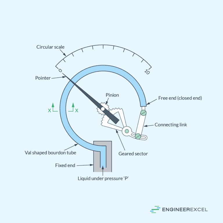
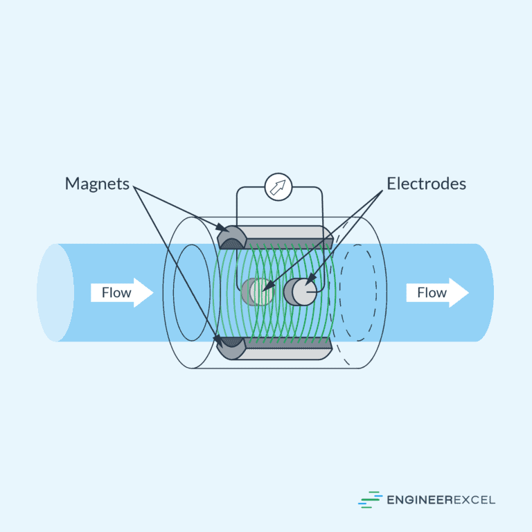
Various devices are employed to measure flow rate in diverse industrial and scientific applications. Flow meters such as pressure differential, electromagnetic, and ultrasonic meters offer precise measurements by leveraging different principles. These devices play an important role in monitoring and controlling fluid flow in sectors ranging from water treatment and oil production to healthcare and laboratory research.
Special Topics in Fluid Dynamics
Water Hammer
Water hammer refers to a pressure surge or wave resulting when a fluid in motion is forced to stop or change direction suddenly. This phenomenon typically occurs in enclosed conduits such as pipelines.
When a valve closes rapidly, it causes a momentum change leading to a rapid rise in pressure known as a hydraulic shock. This can cause significant damage to pipes or fixtures due to the sudden high pressure. Hence, it is essential to design pipe systems in such a way that includes devices like surge tanks or air chambers to mitigate the effects of water hammer.
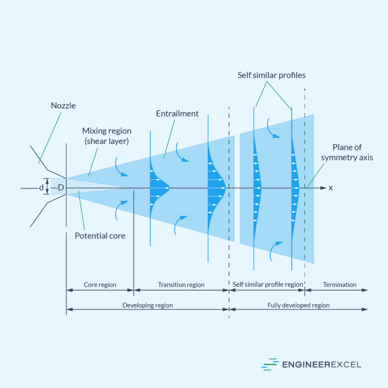
Free Jet
The term “free jet” describes the unrestricted flow of a fluid, usually a liquid or gas, into the surrounding environment without any external confinement. When released from an orifice or nozzle, the fluid expands freely without any boundaries to guide its flow, causing its velocity to decrease as the distance from the discharge point increases. The behavior of a free jet is affected by factors such as the geometry of the nozzle, properties of the fluid, and release conditions.
Free jets are commonly encountered in various engineering applications, including fuel injection systems, water jets, and exhaust from propulsion systems. Understanding the dynamics of free jets is important in designing efficient and controlled fluid flow processes.