
A free jet refers to a fluid flow, typically a liquid or gas, that is ejected into a surrounding medium without any physical boundaries constraining its shape. In this context, the term often describes the unconfined discharge of a fluid stream, such as the spray of water from a nozzle or the exhaust from a jet engine.

In this article, we will discuss the structure of a free jet, factors affecting jet spread, and its practical applications in engineering.
What is a Free Jet
A free jet is a fluid stream that discharges into an expansive medium without any physical confinement. Due to the absence of boundaries that guide its flow, it expands freely upon exiting an orifice or nozzle and its velocity decreases as the distance from the discharge point increases.
The analysis of a free jet usually involves understanding its velocity profile, which describes the distribution of velocity across different sections of the jet. For incompressible fluids such as water, the jet’s core maintains a nearly uniform velocity over a region known as the potential core. Beyond this region, the velocity profile is notably affected by the surrounding medium due to entrainment, where the jet fluid draws in and mixes with the external fluid.

Elevate Your Engineering With Excel
Advance in Excel with engineering-focused training that equips you with the skills to streamline projects and accelerate your career.
In engineering applications, the principles governing a free jet are critical for the design and analysis of various devices, including nozzles, jet pumps, and turbines. For instance, when utilizing jet propulsion, an in-depth comprehension of free jet dynamics enables engineers to optimize thrust production. Here, the ambient pressure plays a vital role, as it influences back pressure on the jet, affecting its spread and eventual dissipation.
Free Jet Structure
The structure of a free jet is characterized by four distinct zones based on the centerline velocity and flow behavior: convergent zone, transition zone, self-similar zone, and termination zone. These are illustrated in the diagram below.
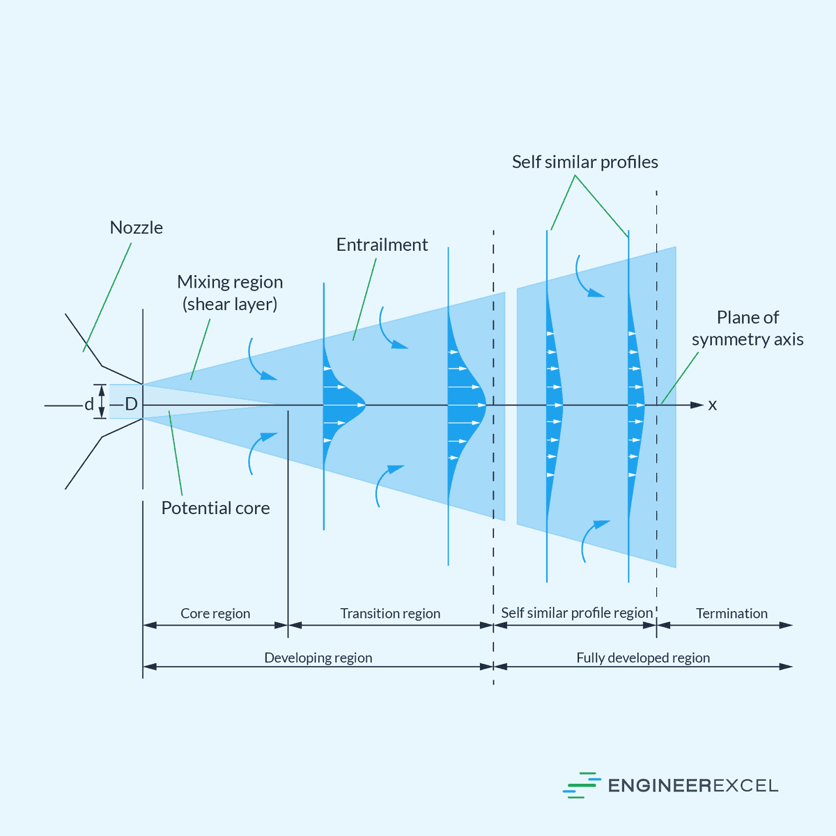
Convergent Zone
In the initial segment of a free jet, known as the convergent zone or the potential core region, the centerline velocity maintains the same magnitude as that at the nozzle’s exit, implying a uniform flow for a certain distance which typically spans 4 to 6 nozzle diameters.
Transition Zone
The transition zone marks the start of velocity decrease along the centerline. Here, velocity attenuation is guided by a relationship inversely proportional to the square root of the axial distance from the nozzle. It is within the bounds of 6 to 20 nozzle diameters that the surrounding shear layers converge.
Self-Similar Zone
Beyond the transition zone lies the self-similar zone, characterized by the resemblance of transverse velocity profiles at varying axial locations. Velocity decay scales with the axial distance, inversely proportional to the distance itself, which substantiates the uniformity of the flow’s shape.
Termination Zone
The termination zone is where the jet’s centerline velocity significantly reduces. This area signifies the collapse and subsequent disintegration of the jet, where it undergoes considerable inward motion from its boundaries before mixing with the ambient fluid.
Factors Affecting Jet Spread
The spread of a free jet is influenced by several critical factors that determine the behavior and characteristics of the jet as it interacts with its surroundings. These factors range from the initial conditions at the jet exit to the properties of the fluid.
Inlet Velocity Profile
The jet’s initial velocity profile sets the stage for its downstream behavior. A laminar profile will generally evolve into instabilities with peak fluctuations near the jet boundaries. Conversely, a turbulent profile features broad spectrum fluctuations.
The typical parameters used to characterize the inlet conditions are the displacement thickness, momentum thickness, and the ratio between these two called the shape factor. The shape factor is 2.5 for a laminar boundary layer at the nozzle exit and 1.4 for fully developed turbulent boundary layer. A value within this range indicates transitional boundary layers.
Nozzle Geometry
Nozzle design also plays an important role in characterizing jet flow. In particular, the cross-sectional shape of the nozzle influences transition and spread rates. Notably, non-circular nozzles may exhibit axis switching due to varying lateral spread rates, whereas circular jets lack this characteristic.
Additionally, nozzle geometry affects the initial velocity profile which can range from saddle-backed for sharp-edged orifices to a top hat profile for smoothly contoured nozzles.
Jet Reynolds Number
The Reynolds number of a free jet can be calculated using the formula:
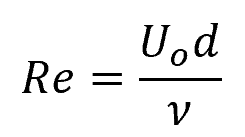
Where:
- Re = Reynolds number [unitless]
- Uo = bulk mean velocity [m/s]
- d = height of the nozzle [m]
- ν = kinematic viscosity of the fluid [m2/s]
Studies show that lower Reynolds numbers lead to reduced dissipation and spread rates, resulting in a narrower jet. In contrast, higher Reynolds numbers lead to increased spread rates, causing the jet to widen more rapidly as it travels downstream from the nozzle exit.
Fluid Temperature at the Inlet
The temperature of the fluid at the intake influences jet spread with variable outcomes for isothermal and non-isothermal conditions. In the former, the jet and ambient temperatures are equal, negating buoyant effects. For non-isothermal flows, temperature differentials introduce complexities in the jet’s spreading dynamics, with buoyant or non-buoyant behaviors altering the spread depending on Richardson number values.
Applications of Free Jet
Free jets are utilized in various engineering and industrial applications due to their unique properties. These high-velocity streams of fluid, unconfined by solid boundaries, have distinct applications based on their capability to deliver energy, momentum, and mass from one point to another effectively.
Water Jet Cutting
A prominent application is in water jet cutting machines that employ high-pressure water jets, sometimes mixed with abrasives, to cut materials like metal, stone, and glass. This precise cutting tool provides several advantages, including minimal material wastage and the ability to cut complex shapes.
- Abrasive Mix: Enhances cutting capability for harder materials.
- Pure Water Jet: Ideal for softer materials like rubber or foam.
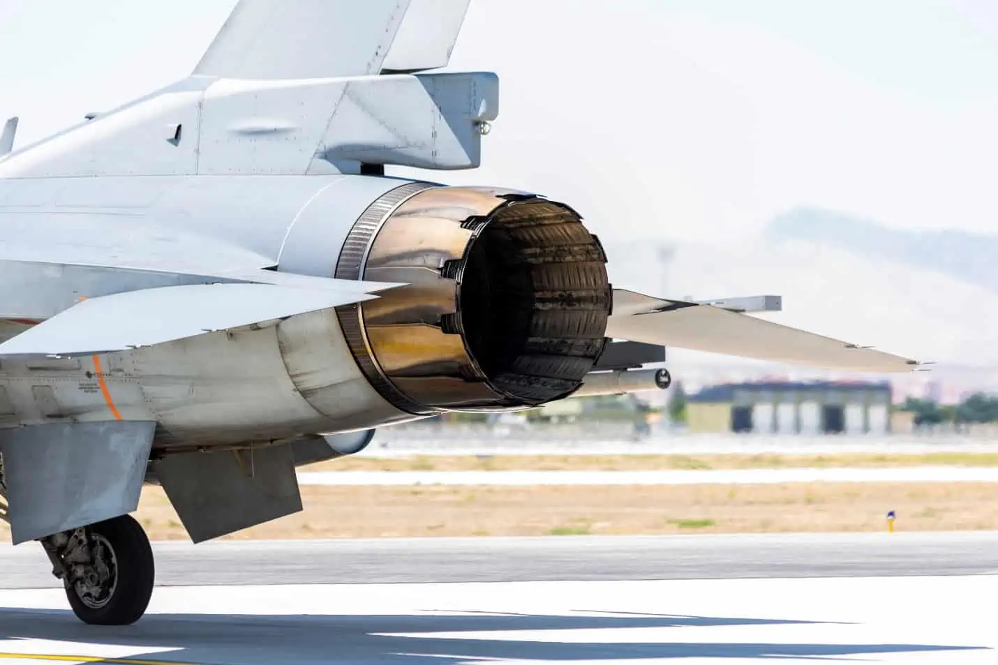
Jet Propulsion
Free jets are fundamental to jet propulsion systems in aerospace engineering. They expel gas at high speed posteriorly to propel the vehicle forward.
- Turbojets and Turbofans: Employed in aircraft engines.
- Rocket Engines: Use free jets to escape Earth’s gravity.
Environmental Engineering
In environmental engineering, free jets are used for aeration in water treatment processes to increase the oxygen content in water bodies, thereby supporting aquatic life and aiding in the breakdown of pollution.
- Oxygenation Level Control: Adjusts the jet’s flow rate and diffusion characteristics.
Combustion Systems
Free jets are critical in the design of efficient combustion systems, such as industrial furnaces and internal combustion engines.
- Fuel-Air Mixing: Optimizes combustion efficiency.
- Emissions Reduction: Aids in controlling pollutant release.