
The friction factor is a dimensionless quantity that is essential in designing and analyzing fluid flow systems in pipes and channels, as it characterizes the resistance to fluid flow and determines the head loss due to friction. Its value varies based on the flow regime. This article specifically focuses on calculating friction factors in the turbulent flow regime.
Friction Factor In Turbulent Flow
When examining the movement of fluids within ducts, channels, and pipes, it is essential to take into account the influence of friction. Friction occurs due to viscous forces, which create shear stresses between adjacent layers of fluid in motion, as well as due to the interaction of the fluid particles coming into contact with irregularities in the surface of the conduit.

As a consequence of friction, energy is lost in the fluid in the form of heat. When designing and analyzing fluid systems, it is crucial to consider these losses, especially when sizing equipment, determining energy requirements, and evaluating system performance. In practice, these losses are quantified using friction factors, which are dimensionless quantities that represent the fluid’s resistance to flow.
In pipes, for example, the head loss due to friction can be calculated using the Darcy-Weisbach equation:

Elevate Your Engineering With Excel
Advance in Excel with engineering-focused training that equips you with the skills to streamline projects and accelerate your career.
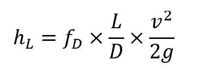
Where:
- hL = head loss due to friction [m]
- fD = Darcy friction factor [unitless]
- L = length of the conduit [m]
- D = hydraulic diameter of the conduit [m]
- v = mean fluid velocity [m/s]
- g = gravitational constant [9.81 m/s2]
The Darcy friction factor is dependent on the Reynolds number, which is a dimensionless parameter used to classify the flow regime. For turbulent flow, there is no precise Reynolds value that universally defines the transition from laminar to turbulent since it can vary depending on the flow conditions and geometry of the system.
However, as a general guideline, flow is typically turbulent for Reynolds numbers above 4000 and laminar for Reynolds numbers below 2000. When the Reynolds number falls between 2000 and 4000, it becomes challenging to predict the nature of the flow accurately; hence, most system designs avoid this transition region.
In the turbulent regime, the flow is characterized by a high ratio of inertial forces to viscous forces, resulting in the formation of eddies and vortices. This chaotic and irregular fluid movement helps overcome the influence of fluid viscosity, reducing the frictional loss caused by viscous forces.
In fully turbulent flows, rather than viscous forces, friction loss is primarily caused by the interaction between fluid particles and surface irregularities or roughness in the pipe. However, in most engineering applications, fully turbulent flows are not common, and the friction factor depends on both the fluid viscosity and the roughness of the pipe surface.
Darcy Friction Factor Calculation In Turbulent Flow
Friction Factor For Smooth-Walled Pipes
In a smooth-walled pipe, the friction factor for turbulent flow is solely dependent on Reynolds number, as shown in the following equation derived by Prandtl:
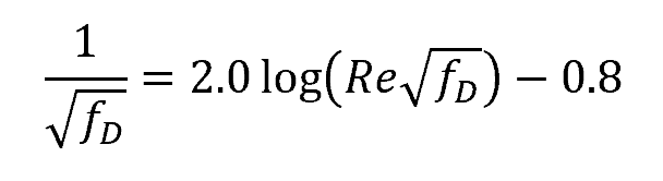
Where:
- Re = Reynolds number [unitless]
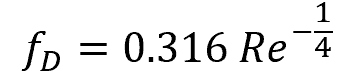
Since Prandtl’s equation above is implicitly structured, many alternative approximations have been developed from which friction factor can be computed explicitly from Reynolds number. One example is the Blasius equation:
Friction Factor For Rough-Walled Pipes
In turbulent flow, unlike laminar flow, the friction factor is significantly influenced by the surface roughness of the conduit. The friction factor increases with the relative roughness, ε/D, of the inner pipe surface, but this increase follows a monotonical pattern. That is, at high Reynolds numbers, the friction factor eventually reaches a stable value and remains constant for a given relative roughness.
This behavior is illustrated in the diagram below.
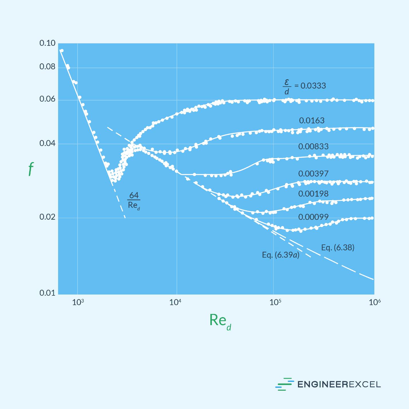
At high Reynolds numbers, the laminar sublayer becomes so thin that the surface roughness protrudes into the flow. In this case, the primary cause of frictional losses is the surface irregularities, while the contribution of the laminar sublayer becomes negligible. For a fully rough flow, the friction factor becomes independent of Reynolds number, as shown in the following formula:
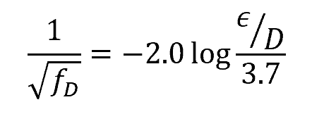
Where:
- ε = average height of surface irregularities [mm or in]
Below is a table of typical roughness values for commercial conduits made of various materials.

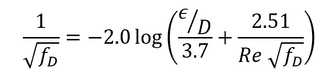
Colebrook Equation
To cover for the transitional rough range, an interpolation formula combining the equations for smooth wall and fully rough flows was developed by Colebrook. This formula is widely accepted as the design formula for turbulent friction:
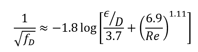
Since the Colebrook equation is implicitly structured, alternative formulas have been developed to explicitly approximate the friction factor. An example of such an equation is the Haaland approximation, which achieves an accuracy of over 98%:
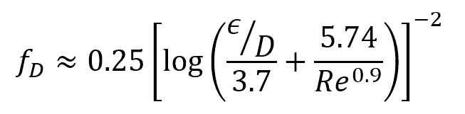
Another example is the Swamee-Jain approximation:
Moody Chart
The values of the Darcy friction factor derived from the Colebrook equation has been plotted by Moody into what is now known as the Moody chart. This chart illustrates the relationship between friction factor, Reynolds number, and relative roughness for a given flow regime, as depicted in the diagram below.
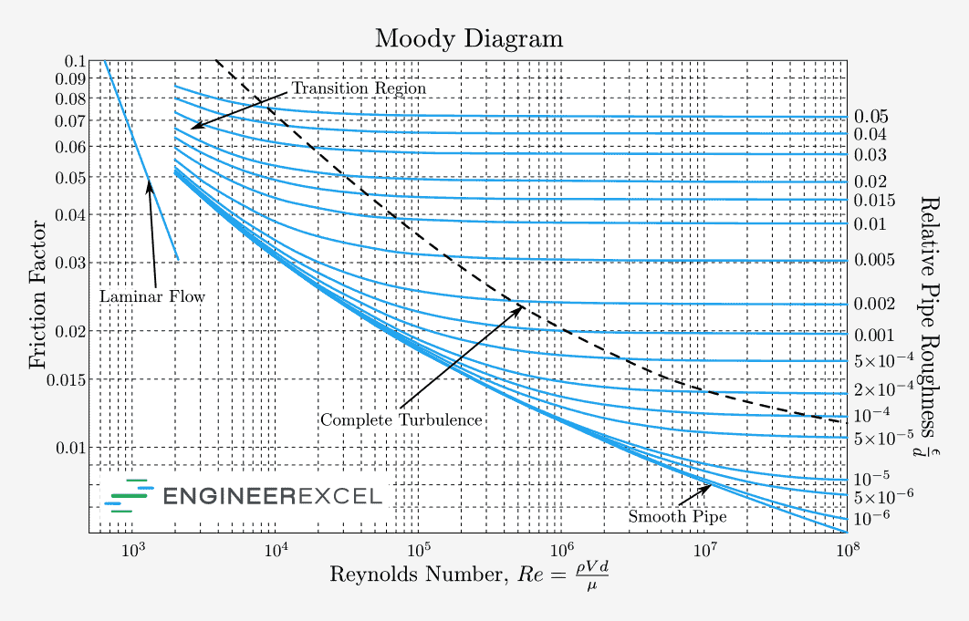
The area on the Moody chart at Reynolds numbers between 2000 and 4000 indicates the range where the transition from laminar to turbulent flow occurs. Within this range, no reliable friction factors are available since the flow in this region is unpredictable, randomly shifting between laminar and turbulent. However, in general, the Moody chart is accurate to within ±15% for design calculations and can be applied to both circular and noncircular pipe flows, as well as open-channel flows.
The Moody chart is a widely used tool by engineers as it simplifies calculations by providing a direct estimation of the friction factor based on known parameters.
Fanning Friction Factor Calculation In Turbulent Flow
The Colebrook equation and the Moody chart both indicate the Darcy friction factor. However, aside from the Darcy friction factor, there exists another factor known as the Fanning friction factor, which finds wide application in the field of chemical engineering and in calculations involving British units.
The Fanning friction factor is just equivalent to one-fourth of the Darcy friction factor. Therefore, the same set of formulas that employ the Darcy friction factor can be utilized to calculate pressure loss using the Fanning friction factor, with the only difference being the division of the friction factor value by a factor of 4.
Turbulent Flow vs Laminar Flow Friction Factor
The method of obtaining the friction factor varies depending on whether the flow is laminar or turbulent.
In laminar flow, the fluid flows smoothly in parallel layers and the frictional losses are primarily caused by the viscous shearing between streamlines near the wall of the pipe. The friction factor in this regime is directly proportional to the shear stress, which, in turn, depends on the viscosity of the fluid and the velocity gradient across the flow.

In contrast, turbulent flow is characterized by the random movement of eddies and vortices. In the turbulent regime, the effect of viscous forces on frictional loss is reduced due to the chaotic nature of fluid flow. Unlike laminar flow, the friction factor in turbulent flow is heavily influenced by the interaction between fluid particles and surface irregularities or roughness within the conduit.
Because of the predictable nature of laminar flows, the friction factor can typically be determined using analytical equations based on fundamental principles. On the other hand, due to the random and complex nature of fluid movement in turbulent flows, determining the friction factor requires the use of empirical data and correlations obtained from experiments.
Generally, laminar flows have a higher friction factor compared to turbulent flows, as depicted in the Moody chart. However, it is important to understand that a higher friction factor does not always translate to higher frictional loss.
This is because frictional loss is affected by and directly proportional to the square of fluid velocity. Since turbulent flows typically exhibit higher velocities than laminar flows, they ultimately result in higher frictional losses.