
The Energy Gradient Line (EGL) is a hypothetical line representing the total energy per unit weight of a fluid particle as it moves along a streamline in a fluid flow system. It combines the effects of both potential and kinetic energy, providing a useful reference for analyzing the energy distribution in open-channel flows or pipelines.
In this article, we will discuss the components of the EGL, the comparison between EGL and Hydraulic Gradient Line (HGL), as well as the applications of EGL in fluid mechanics.
What is the Energy Gradient Line
The Energy Gradient Line (EGL) is a graphical representation that shows the total head available to fluid flow in a pipe or channel. Expressed in terms of energy per unit weight, the line depicts the height of the energy head when plotted along the path of the flow. It typically starts from the total head at the source and decreases along the flow path due to energy losses, primarily from friction and minor losses like bends, fittings, and valves.
By evaluating the EGL, engineers can design systems to minimize energy losses and optimize fluid transport efficiency. It aids in the prediction and management of flow patterns and ensures the successful operation of hydraulic systems.

Elevate Your Engineering With Excel
Advance in Excel with engineering-focused training that equips you with the skills to streamline projects and accelerate your career.
Components of the Energy Gradient Line
The total energy represented by EGL can be divided into three components: pressure head, elevation head, and velocity head.
Pressure Head
The pressure head represents the energy due to the pressure of the fluid. Mathematically, it is given by the formula:

Where:
- hP = pressure head [m]
- P = fluid pressure [Pa]
- ρ = density of the fluid [kg/m3]
- g = gravitational acceleration [9.81 m/s2]
Elevation Head
The elevation head represents the gravitational potential energy of the fluid. It is the energy per unit weight associated with the height of the fluid above a reference plane. Mathematically, it is given by the formula:
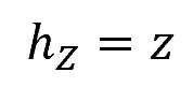
Where:
- hz = elevation head [m]
- z = vertical distance of the fluid element above the reference plane [m]
Velocity Head
The velocity head represents the kinetic energy of the fluid due to its velocity. It is the energy per unit weight associated with the motion of the fluid. Mathematically, it is given by the formula:
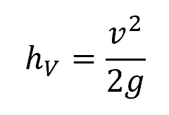
Where:
- hV = velocity head [m]
- v = fluid velocity [m/s]
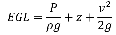
Combining all of these components together, the total head represented by EGL can be computed as follows:
Energy Gradient Line vs Hydraulic Gradient Line (HGL)
The Hydraulic Gradient Line (HGL) is a concept closely related to the Energy Gradient Line (EGL). While the EGL includes all forms of energy (potential, kinetic, and pressure), the HGL focuses specifically on pressure and elevation energy. Hence, EGL is always above the HGL, as illustrated in the diagram below.
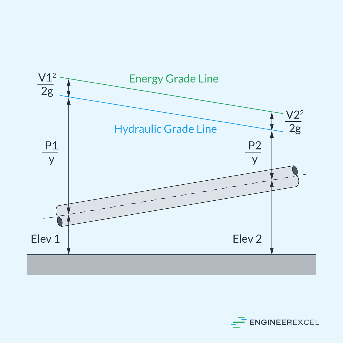
The separation between these lines equates to the velocity head and their slopes correlate with energy loss. Steep gradients indicate higher losses, while gradual gradients indicate lower losses.
In an ideal scenario without friction—hence no energy loss—the EGL remains at a constant height, as shown in the diagram below.
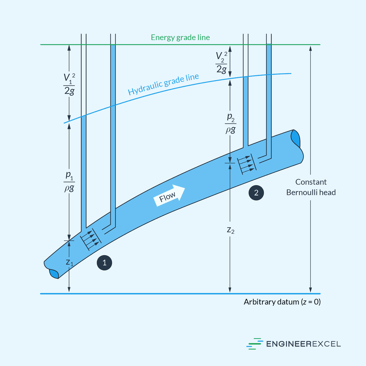
This scenario is mathematically expressed by the Bernoulli Equation, which is applicable for incompressible, steady, one-dimensional flow:
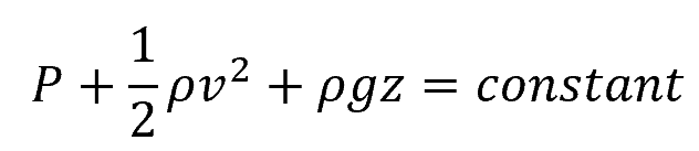
However, real-world conditions introduce frictional forces that result in a gradual decline of the EGL along the direction of flow. Abrupt energy losses, like those due to valves or obstacles, or energy extraction processes such as those involving turbines, lead to steep drops in the EGL.
Conversely, an increase in the EGL occurs only through work addition, as when a pump introduces energy into the flow. The behavior of the HGL typically mirrors the EGL, rising or falling with the decrease or increase in flow velocity, respectively.
It is critical to understand that in an open-channel flow, the HGL and the free surface of the water align, while in closed conduits, the EGL and HGL can be visualized using pitot tubes for the velocity head and piezometer tubes for static pressure head. Observing these grade lines helps engineers anticipate how water will behave under various conditions, essential for designing efficient systems for water transport and energy extraction.
Applications of Energy Gradient Line
Pipe Flow Analysis
In pipe flow analysis, the EGL is instrumental in determining the efficiency and viability of a fluid transport system. When assessing energy losses, particularly in the form of head loss due to friction and minor losses, engineers use the EGL to ensure that sufficient energy is available to overcome these losses and maintain required flow rates.
Open Channel Flow
In open channel flow, the EGL serves as an essential reference for water conveyance in structures such as canals, rivers, and drainage systems. The slope of the EGL can help predict how the flow will behave—whether it will be subcritical or supercritical—and assists in the design of channels to prevent issues like flooding or inefficient water delivery.
The elevation of the EGL relative to the channel bed also provides insights for managing energy dissipation, which is crucial for structures like spillways and weirs. Accurate analysis of the EGL in open channel flow not only optimizes hydraulic performance but also impacts the management of water resources and environmental considerations.