
Flow measurement is the quantification of the rate at which a fluid, such as a liquid or gas, moves through a system or conduit. It is essential for the accurate monitoring and control of fluids in industries ranging from water treatment to oil and gas.
In this article, we will discuss the different types of flow measurement devices, along with their operational principles, applications, and installation considerations.
Introduction to Flow Measurement
The origin of flow measurement dates back to ancient civilizations, where it played an important role in managing water resources.
Scholars like Aristotle and Archimedes made pioneering contributions that laid the foundation for fluid dynamics, leading to further advancements by scientists such as Daniel Bernoulli and Sir Isaac Newton. Their work forms the basis for modern flow measurement technologies.

Elevate Your Engineering With Excel
Advance in Excel with engineering-focused training that equips you with the skills to streamline projects and accelerate your career.
For instance, Bernoulli’s principle, which states that an increase in fluid velocity results in a decrease in static pressure and potential energy, is fundamental to various flow-measuring devices like Venturi meters, Pitot tubes, and orifice plates. These devices use the principle to estimate fluid flow rates by measuring pressure changes associated with variations in fluid velocity.
In modern engineering, flow measurement devices, or flowmeters, come in different types, each with its own operational principle, maintenance requirements, fluid limitations, installation constraints, and level of accuracy. These factors must be carefully considered to ensure precise and reliable measurements.
Today, flow measurement technologies are continually advancing, incorporating advanced materials, electronics, and computational methods to improve accuracy and functionality. Nevertheless, errors can still occur due to improper installation, calibration, or the use of flow meters that are incompatible with fluid properties or flow conditions. Therefore, ensuring accuracy and repeatability remains vital.
Types of Flow Measurement Devices
Differential Pressure Flow Meters
Differential Pressure (DP) Flow Meters operate on the principle of measuring the pressure drop over an obstruction inserted in the fluid flow path. By calculating this pressure differential, one can derive the flow rate. Common examples include orifice plates, venturi tubes, and flow nozzles, shown in the diagram below.
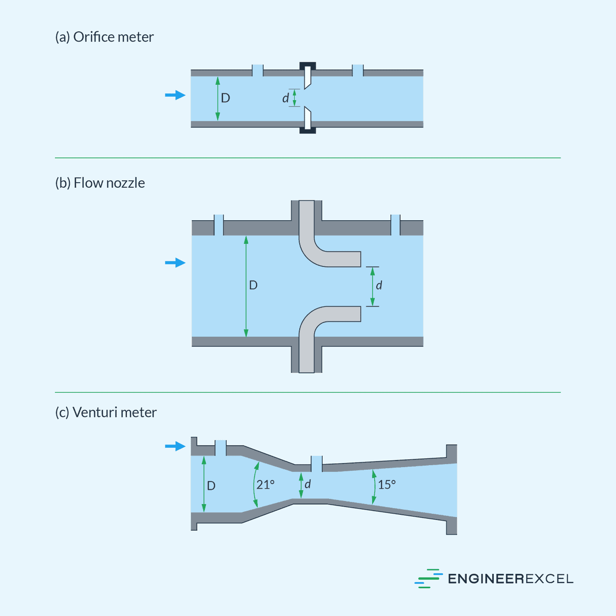
An orifice plate is a simple, flat plate with a hole drilled through its center. The orifice can be round, square, or another shape.
On the other hand, a flow nozzle has a converging inlet and a throat that typically has a smaller diameter, causing a pressure drop.
Lastly, a venturi tube has a gradually converging inlet section, followed by a throat, and then a gradually diverging outlet section. The throat is the narrowest part, creating a pressure drop.
Venturi tubes generally offer the highest accuracy among the three, but each device has its own advantages and limitations depending on the specific application and required precision.
Mechanical Flow Meters
Mechanical flowmeters are devices used to measure the flow rate by using moving components that are displaced by the fluid and then converting the movements into flow rate readings. These include positive displacement flowmeters, turbine flowmeters, and propeller flowmeters.
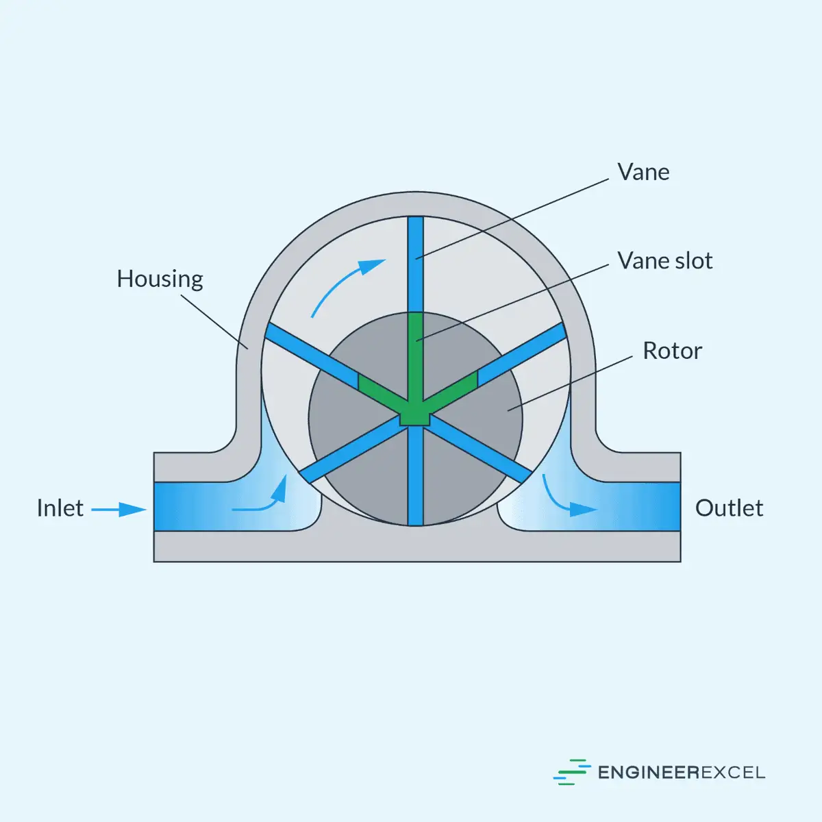
Positive Displacement Flowmeters
Positive displacement flowmeters measure flow rate by trapping fluid in compartments and counting the number of times these compartments are filled and emptied. Accuracy is a hallmark of these meters, making them suitable for measuring viscous fluids or for applications requiring precise volumetric readings.
Turbine Flowmeters
Turbine flowmeters determine the velocity of a fluid flowing through them. A rotating turbine wheel is placed in the flow stream; fluid velocity is proportional to the turbine’s rotational speed. Key considerations for turbine flowmeters include maintaining a consistent flow profile and preventing damage from particulates in the fluid.
Propeller Flowmeters
Propeller flowmeters feature a propeller that is rotated by the fluid flow. The flow rate is inferred from the rotational speed of the propeller which is directly related to the fluid’s speed. They are commonly used in large diameter irrigation and water distribution systems. Their primary trade-off is low cost and low accuracy.
Paddlewheel Flowmeters
Paddlewheel flowmeters possess a wheel with paddles that extend into the fluid flow. As the flow turns the wheel, sensors detect the rotations to calculate the flow rate. They are easy to install and maintain, making them popular for applications where low cost and ease of use are priorities.
Electronic Flowmeters
Electronic flowmeters are favored for their accuracy, reliability, and the ability to measure flow without obstruction. This category includes magnetic, vortex, and ultrasonic flowmeters.
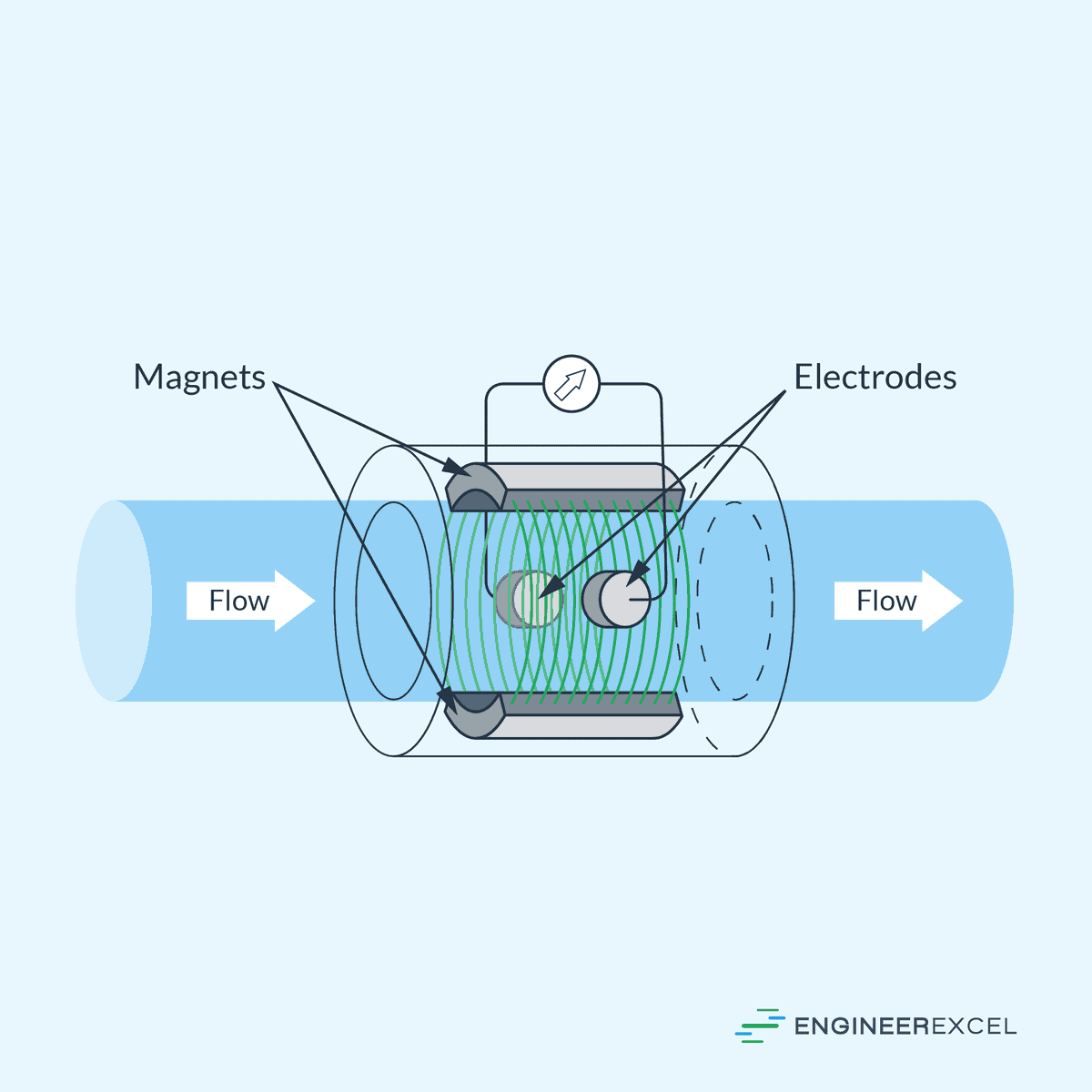
Magnetic Flowmeters
Magnetic flowmeters operate on Faraday’s Law of electromagnetic induction, which dictates that a voltage will be induced when a conductive fluid flows through a magnetic field. The voltage produced is directly proportional to the fluid’s velocity.
Installation requirements include ensuring the fluid is electrically conductive, and the pipe is non-conductive to avoid signal dampening. An important benefit of magnetic flowmeters is their non-intrusive nature, maintaining the integrity of the processed fluid without pressure drop.
Vortex Flowmeters
Vortex flowmeters measure the vortices produced by fluid passing a bluff body. The number of vortices is counted, which is proportional to fluid velocity. As flow increases, so does the frequency of vortex shedding, allowing the flowmeter to correlate this frequency to the volumetric flow rate.
They typically require a straight run of pipe for accurate measurement and are less affected by changes in fluid properties. Vortex meters are advantageous for their robust sensor life and low maintenance requirements.
Ultrasonic Flowmeters
Ultrasonic flowmeters determine flow rate by sending ultrasonic sound waves through the fluid and measuring the time it takes them to traverse the pipeline. There are two main types: Doppler and transit-time. Doppler ultrasonic flowmeters require particulates or bubbles in the fluid to reflect sound waves, while transit-time meters measure the time difference between upstream and downstream wave travel.
Their typical use cases include clean fluids where maintaining flow integrity is critical. Ultrasonic meters are highly accurate and ideal for applications where the fluid cannot be contaminated.
Mass Flowmeters
Mass flowmeters quantify the mass flow rate of a fluid traveling through a tube. These meters are essential for applications requiring precise measurements of mass flow, such as chemical reactions and thermal transfers.
Coriolis Mass Flowmeters
Coriolis mass flowmeters function on the basis of the Coriolis effect. As fluid passes through a vibrating tube, the Coriolis force is exerted on the fluid particles traveling through the tubes, causing a measurable phase shift. This shift is directly proportional to the mass flow rate and is detected by sensors.
Thermal Mass Flowmeters
Thermal mass flowmeters utilize a heated element in contact with the flowing fluid and measure the heat dissipation to determine the mass flow rate. There are two primary sensor designs:
- Constant Temperature Anemometer (CTA): Maintains a constant temperature differential between the fluid and the heated sensor.
- Constant Power Anemometer (CPA): Supplies constant power to the heater and monitors the temperature increase.
Installation Considerations
When installing flow meters, engineers must consider several critical aspects to ensure accurate readings and long-term reliability. These aspects include correctly sizing the flow meter, choosing the optimal location, and employing best practices.
Flow Meter Sizing
Selecting the suitable size of flowmeter is important, as improper sizing can lead to inaccurate measurements and operational inefficiencies. An oversized meter might cause low flow sensitivity, whereas an undersized one can restrict flow and create undue pressure drop. Engineers should refer to the manufacturer’s specifications and consider the minimum and maximum flow rates of the system when selecting a flow meter size.
Meter Location
Installing the flowmeter in an appropriate location is also important. For example, the meter must be positioned in a section of the pipe where the flow profile is fully developed, typically several diameters downstream from bends, valves, or other disruptions. Straight runs of pipe, both upstream and downstream, as specified by manufacturers, are critical for avoiding turbulence that can skew the measurement.
Installation Best Practices
The installation process demands precise practices to protect the accuracy and lifespan of the flow meter. It includes:
- Securing a proper fit: Assuring that the meter is properly aligned and connected to the piping system without any strain.
- Preventing blockages: Installing filters or strainers upstream to prevent debris from obstructing the flow meter mechanism.
- Lifts for backfilling (if applicable): When installing a flow meter in a buried pipe, compact the backfill in lifts to avoid pipe deformation.
- Verification after installation: Testing the installation by performing a flow measurement to confirm that the flow meter operates within the expected range of accuracy.