
The hydraulic gradient line represents the total piezometric head of water along a flow path in a hydraulic system, incorporating both elevation head and pressure head. It is a graphical representation that helps visualize the energy distribution in a fluid flow and is crucial for analyzing and designing hydraulic systems.

In this article, we will discuss the components of the Hydraulic Gradient Line, its comparison with the Energy Gradient Line, and its role in designing pipe networks and open channels.
What is the Hydraulic Gradient Line?
The Hydraulic Gradient Line (HGL) is an imaginary line that traces the piezometric head of the fluid flowing through a system. The line typically starts from the maximum piezometric head at the source and then decreases along the flow path due to pressure losses caused by friction and minor losses such as bends, fittings, and valves.
The HGL shows the hydraulic energy available to propel the fluid through a system. This allows engineers to evaluate flow conditions in applications such as stormwater drainage, irrigation systems, and municipal water supply networks. Assessing the HGL helps identify potential points of overflow or underperformance to prevent issues like flooding or cavitation.

Elevate Your Engineering With Excel
Advance in Excel with engineering-focused training that equips you with the skills to streamline projects and accelerate your career.
Components of the Hydraulic Gradient Line
The piezometric head represented by HGL can be divided into two components: pressure head and elevation head.
Pressure Head
The static pressure head represents the potential energy due to fluid pressure, measured in terms of equivalent fluid height. It is given by the formula:
Where:
- hP = static pressure head [m]
- P = fluid pressure [Pa]
- ρ = density of the fluid [kg/m3]
- g = gravitational acceleration [9.81 m/s2]
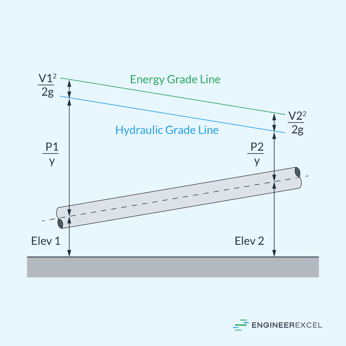
In a pipeline, the pressure head is indicated by the vertical distance between the HGL and the actual fluid level, as shown in the diagram above.
Elevation Head
Elevation head refers to the vertical distance of a fluid above a datum level, which is usually the lowest point of the hydraulic system. This component of the HGL represents the potential energy of the fluid due to gravity, and is expressed as:
Where:
- hz = elevation head [m]
- z = vertical distance of the fluid element above the reference plane [m]
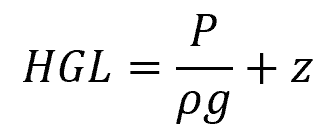
Combining both of these components together, the total piezometric head represented by the HGL can be computed as follows:
Hydraulic Gradient Line vs Energy Gradient Line
Hydraulic Gradient Line (HGL) and Energy Gradient Line (EGL) are both graphical representations used to design and analyze the behavior of flowing fluids, such as water, within a closed conduit or open channel.
While the HGL only indicates the energy available due to elevation and pressure, the EGL includes all forms of energy within the system: kinetic, potential, and pressure energy. Therefore, the EGL is always above the HGL, assuming there is flow velocity.
The difference between EGL and HGL is indicative of velocity head and represents the kinetic energy of the flow per unit weight of fluid, as shown in the diagram above. In a horizontal pipe with steady, uniform flow, the HGL and EGL will be parallel, and their separation distance will be constant.
Hydraulic Gradient Line in Pipe Networks
In pipe flow, the HGL is separated from the pipe elevation by the static pressure head. When the HGL falls below the pipe elevation, it indicates negative gauge pressure or pressure lower than atmospheric.
This situation is generally undesirable because foreign matter may be drawn into the pipe through any leaks, and extremely negative gauge pressures can cause dissolved gases to come out of solution, leading to cavitation damage. Hence, during the design phase, the HGL must be carefully plotted above the ceiling of the pipe to avoid creating vacuum conditions.
For gravity pipe networks, it is important that the pipes have sufficient slope to allow for the expected flow volumes. Additionally, pipes need to be adequately sized and placed to minimize potential damage.
The slope of HGL is given by the equation:
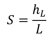
Where:
- S = slope of HGL [unitless]
- hL = head loss [m]
- L = pipe length [m]
In pipe networks, the HGL is influenced by several factors including:
- Pipe Diameter: Affects the velocity of flow and, subsequently, the head loss.
- Pipe Roughness: Influences the friction and energy loss over a distance.
- Fittings and Valves: Cause local losses and can create a significant drop in the HGL.
Hydraulic Gradient Line in Open Channels
In open channels, since pressure is atmospheric at the surface, the HGL is simply the height of the free surface when the flow is tranquil. Its slope is typically parallel to the bottom slope in uniform flow scenarios. However, in non-uniform or rapidly varied flow, it may exhibit a distinctly different HGL slope.
A typical HGL analysis of an open channel involves assessing inflow and bottom slope conditions, estimating friction and other local losses, and computing the depth at successive sections based on flow continuity and energy principles. Accurate plotting of the HGL ensures the prevention of overtopping and affords stability to the surrounding environment, which is vital for sustaining channel structural integrity.
Example Problem
Problem: A water tank is located at an elevation of 20 meters above a certain point. The pressure at the bottom of the tank is measured to be 300 kPa. Calculate the height of the hydraulic grade line at the bottom of the tank.
Solution:
The height of the hydraulic grade line or the piezometric head can be calculated using the following equation:
Assuming the density of water is 1000 kg/m3 and plugging in the given values into the equation:
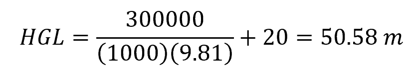
Therefore, the height of the hydraulic grade line at the bottom of the tank is 50.58 meters.